I am still interested in your developments, so, please, keep us informed
I am joining a new audiophile club, and those guys are on line...we are making group constructions, and i will submit your amplifier to their apreciation.
I will be happy if they agree to another group assembling, this time, using your Gem design.
Your search of perfection already achieve a very good level, as you started from a wonderfull amplifier, the JLH designs, perfectioned when you made your 25 Watts unit, and now, many versions of AABB.
I will be happy to know, using direct mailing, the real advantages you felt using those new transistors...no!, i am not talking about measurements, i am talking what you perceived when jumped to top level output devices and the very good 2N5401.... some MPSa18 can be good too...but it can oscilate in wide band, can amplify FM broadcasting too....i do not know if this is solution or problem, when you have those Radio frequency transistors, those ones capable of oscilating in so high frequencies.
Well Mr. Graham, not needed to say the respect i have to your person, and because of that, i am asking you the kindness to keep me informed related each step you do inside your laboratory.
I will be happy to know the moments where something fail, and you conclude the reason why...this is wonderfull knowledge to me.
We learn more when we fail.
regards,
Carlos
Hi Carlos,
Very good to hear that you will be active with amplifiers again.
It would be excellent if your group could keep notes for later comparisons, and I trust they will do as you used to; ie. listen to the sound, and not just measure with instruments. Maybe you could even keep the odd successful basic amplifier chassis minus power supply for later comparisons.
Transistors. I judge that the modern output devices produce a finer accuracy to sound, as long as they can be kept from oscillating that is. I find a lower resistance or second Zobel of help here, say 0.01 or 0.022uF in series with 2.2 or 4.7 ohms.
MPSA18;- I used to make whip antenna buffer amplifiers with those. Lower internal capacitance and higher gain than BC types, but also a slightly higher internal resistance.
For inputs I prefer to stick to BC546B/BC556B because noise is not a problem, and I would use 2N5400/1 and 2N5550/1 because they are widely available and completely adequate for the higher voltage small low current stages.
Haven't been able to get the soldering iron turned on for several weeks now, what with one thing or another.
As long as there is always something to fall back on then at least failure is not a disaster, but I'll most certainly let you know if I need to borrow your 12 bore to eliminate the occasional horror!!!
Cheers ......... Graham.
PS. If you build the last AABB I have a typo on the upper inductor. It should be 22uH and not 150uH. Also keep the pre-driver separately heatsinked.
Thank you Graham, better health to you, take care.
I perceive the inductor, already noticed.
This is good, to separate thermically the drivers from output, as this can turn a snow ball rolling down mountain.
I am trying to calculate your circuit, to understand it deeply, it is a hell clever and simple.
Yes!, simple things turn live better... a good wife, children and simple amplifiers to produce good sound.
regards,
Carlos
Graham,
What do you think of using a set of darlington output devices?
/edit: I mean ready-made darlingtons. TIP132 type (ugh, but it's off the top of my head), not a combination of a pair of discretes.
What do you think of using a set of darlington output devices?
/edit: I mean ready-made darlingtons. TIP132 type (ugh, but it's off the top of my head), not a combination of a pair of discretes.
My God Graham, this is gênius work!
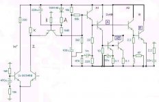
The stabilized supply, working as stabilizer and impedance buffer, only three stages, without gain losses...this is wonderfull.
The B is not really pure B, it is third instance acting AB unswitching circuit.... the frequency dividers you have in each stage, the timming between them, they will go on in different timmings, the coil will charge when hi frequencies tried to cross and produce treble dinamics!... the bass boost hidden....my God Graham!, no one can produce something so clever as you made.
I cannot think in another thing but this amplifier. Both halves working exactly the same timming...this will keep switching hidden in small pulses never perceived by normal ears!
You are incredible, please, send another picture with signature...that one was lost when HD burn...i promiss, this new one will go to a diskette and maybe to a backup CD.
This amplifier explained in details show the creative gênius, using simple ideas.... and clever.... really clever.
Not complicating.... easy!, very easy to understand...the timmings are great!!!
regards,
Carlos
In fact, the simple triple-follower with cross-coupled drivers as used in the 'Leach-Amp.', does, (with proper biasing and cross-coupling resistors), run the first driver in class-A, the second in AB,
while the output is biased in B.
It's closed-loop performance is unsurpassed as far as i know.
while the output is biased in B.
It's closed-loop performance is unsurpassed as far as i know.
hummmm, by the way Mikeks, you are so beautifull in this picture
I can see also a lot of qualities in your avatar.... this is hiper sensorial long distance triple dear perception.
hehe.
Glad to meet you again.
Carlos
I can see also a lot of qualities in your avatar.... this is hiper sensorial long distance triple dear perception.
hehe.
Glad to meet you again.
Carlos
A lot of success in Essex Mike...that was deep.
A long time i do not met you, and despite not too much sunshine in UK, you continue with a beautifull sunny color.
Yesssss
Carlos
A long time i do not met you, and despite not too much sunshine in UK, you continue with a beautifull sunny color.
Yesssss
Carlos
Hi Carlos,
I'm feeling a little drained at the moment, maybe back later or tomorrow.
First circuit had a lower base-emitter resistor for the 'B' output.
Design still not finalised, more thought needed.
I noticed you said a 'good' wife and 'simple' amplifier, and not the other way around.
Cheers for now ......... Graham.
A new globalized world, all things changing, and i am going changing my mind too.
Health to you, this design is wonderfull.
No problem the class B with some bias.... just beeing a little flexible...hummm, some exotic class B...i love that!
Yeah, talking serious, i am having fun with that, the good mood inserted under the substract of your deep examination, this made me realise that the stage will work more linear when excited with high frequencies, beeing less efective with low, because of the coil...this was great!
If the "Chiro" doctor produced that result, despite headaches, i will find him to make the same on me.... some pain to produce those nice ideas.... deal made man!
regards,
Carlos
Oh!...do not tell people....oh!...this will be our secret..
Do not let them know that.... competition!
Hello Graham!
He is busy and a litle sick...sent me two lines saying a hell busy now.
regards,
Carlos
Do not let them know that.... competition!
Hello Graham!
He is busy and a litle sick...sent me two lines saying a hell busy now.
regards,
Carlos
- Status
- Not open for further replies.
- Home
- Amplifiers
- Solid State
- Class-AABB output stage.