
Two (2) MJ15003 & 2 MJ15004 at the output, push pull, Vcc 65v @ 1.5Amps continous at no load. I want to know the collector emitter voltage. ThanksDepends on the class A bias setting, and the making of the output transistors.
So what's the bias current, and which bjt's are involved?
It is unusual to have so much voltage in a Class A amplifier.Vbe and Vce of output transistors in Class A with 65v Vcc at 6 ohm load?
There will be so much heat.
Requires strong transistors and a very large heatsink.
It can be done but is very difficult.
Aside: I recommend to distinguish fundamentally between single ended and push pull. Many think that only "Class A" is important. But it is perceptible to the ear whether ONE signal goes through ONE part or through TWO different sounding parts. The same number of "steps" is required.
How about measuring it?Two (2) MJ15003 & 2 MJ15004 at the output, push pull, Vcc 65v @ 1.5Amps continous at no load. I want to know the collector emitter voltage. Thanks
But. Is Vcc connected to the collector, and the emitter to the output which is zero? There's your answer.
As Nelson asked, is it +/-32.5V? Then each collector is at +32.5 or -32.5 and each emitter close to zero.
Does that answer your question?
If not, post a schematic and all will be clear.
Edit: as any data sheet will tell you, Vbe will be anywhere between 0.5V and 0.8V depending on the transistor type and the collector current.
Again, easlily measured.
Jan
Last edited:
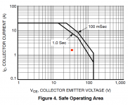
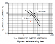
SOA of both, A-setting in red square (closing to the edge, not much margin left on the right side).
Active cooling of the heat sinks may be neccessary (noise!).
Datasheet provided to determine the Vbe's.
Beta is acceptable. What drivers?
Active cooling of the heat sinks may be neccessary (noise!).
Datasheet provided to determine the Vbe's.
Beta is acceptable. What drivers?
Attachments
it's dual supply, but i dont get half of 65v at collectr emmiter, i am getting 58v and the transistors blow burning smell when i turn the bias up..Single ended supply? 65/2 = 32.5 V
thanks sirIt is unusual to have so much voltage in a Class A amplifier.
There will be so much heat.
Requires strong transistors and a very large heatsink.
It can be done but is very difficult.
okayHow about measuring it?
But. Is Vcc connected to the collector, and the emitter to the output which is zero? There's your answer.
As Nelson asked, is it +/-32.5V? Then each collector is at +32.5 or -32.5 and each emitter close to zero.
Does that answer your question?
If not, post a schematic and all will be clear.
Edit: as any data sheet will tell you, Vbe will be anywhere between 0.5V and 0.8V depending on the transistor type and the collector current.
Again, easlily measured.
Jan
The reason I asked for the schematics is this:
So, that might be 1.4A per each "branch"...??? I.e. 2.8A at 65V...???
Two (2) MJ15003 & 2 MJ15004 at the output, push pull, Vcc 65v @ 1.5Amps continous at no load. I want to know the collector emitter voltage. Thanks
So, that might be 1.4A per each "branch"...??? I.e. 2.8A at 65V...???
Push Pull and 1 time 65 V = 32,5 V offset (output). And an output cap. Usually.Two (2) MJ15003 & 2 MJ15004 at the output, push pull, Vcc 65v @ 1.5Amps continous at no load. I want to know the collector emitter voltage. Thanks
Push Pull and 2 times 65 V (65 V + and 65 V -) = 0 V offset (output), usually.
1 time 65 V or 2 times 65 V and you are "getting 58 v" "offset" (output): something is defect. Or an error has crept in. Usually.
2 times 65 V and 2 x 2 output-transes and fat Classe A is not usual. You could, should drive a smaller bias. The sound will not be worse: a little more disembodied.
But you will show the schemata;-)
Last edited:
yes now i measured collector current of each 3 npn output transistors, and shows me 650mA and collector emitter is 63v almost the supply voltage, accordng to nelson pass must be 32.5v to be at class A? it seems my amplifier is not class AThe reason I asked for the schematics is this:
So, that might be 1.4A per each "branch"...??? I.e. 2.8A at 65V...???
If collector-emitter is 63V, there are two possibilities: the amp has two power supply voltages, +65V and -65V, which is very unlikely.
Other possibility is that the amp has + and - 32.5V supply and the output is slammed to one of the supplies.
If you don't post a schematic, you're going around in circles for the next few years and nobody can help you.
Won't you just read what is posted here and act on it for a change?
It's very disrespectful to ask for help and then totally ignore it.
Jan
yes the supply is +65v and -65v, now i measured collector current of each 3 npn output transistors, and shows me 650mA and collector emitter is 63v almost the supply voltage, accordng to nelson pass must be 32.5v to be at class A? it seems my amplifier is not class A, How would i make Vce much less 65v?If collector-emitter is 63V, there are two possibilities: the amp has two power supply voltages, +65V and -65V, which is very unlikely.
Other possibility is that the amp has + and - 32.5V supply and the output is slammed to one of the supplies.
If you don't post a schematic, you're going around in circles for the next few years and nobody can help you.
Won't you just read what is posted here and act on it for a change?
It's very disrespectful to ask for help and then totally ignore it.
Jan
- Home
- Amplifiers
- Solid State
- Class A