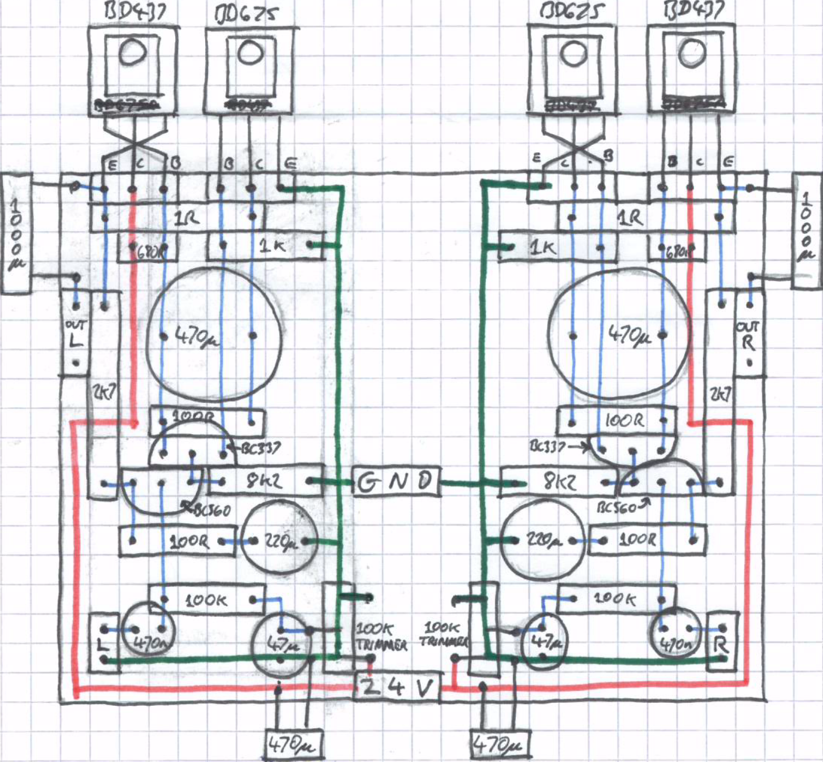
I've built an amp based on the circuit here:
7 Watt Class-A Audio Amplifier - RED - Page177
Here is my layout:
Front:
https://dl.dropboxusercontent.com/s/i62d4v2bq21m7ec/2016-04-24%2014.44.32.jpg
Back:
https://dl.dropboxusercontent.com/s/hc8awal8ca04f7a/2016-04-24%2014.45.28.jpg
I'm powering it with a bench power supply, set to 24V and 1A. As described in the article, I've connected the pot and turned it fully anti-clockwise, I then tried turning the trimmers to set the voltage at C6 to 12V however the bench power supply starts switching when I approach this value with the full 1A being drawn. No matter what current limit is set (up to 2A) all of it is sunk.
I've repeatedly checked the component values and the routing and have found no error.
This layout apparently works, its taken from a Philippine forum which has been deleted in the last couple of days:
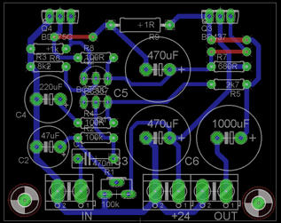
However from my analysis I've found that this layout should not work as the emitter and collector of Q1 (BC560C) are the wrong way round.
Is my problem caused my using a bench power supply?
Or is there an error in how I translated the schematic into the layout in the top image?
7 Watt Class-A Audio Amplifier - RED - Page177
Here is my layout:
Front:
https://dl.dropboxusercontent.com/s/i62d4v2bq21m7ec/2016-04-24%2014.44.32.jpg
Back:
https://dl.dropboxusercontent.com/s/hc8awal8ca04f7a/2016-04-24%2014.45.28.jpg
I'm powering it with a bench power supply, set to 24V and 1A. As described in the article, I've connected the pot and turned it fully anti-clockwise, I then tried turning the trimmers to set the voltage at C6 to 12V however the bench power supply starts switching when I approach this value with the full 1A being drawn. No matter what current limit is set (up to 2A) all of it is sunk.
I've repeatedly checked the component values and the routing and have found no error.
This layout apparently works, its taken from a Philippine forum which has been deleted in the last couple of days:
However from my analysis I've found that this layout should not work as the emitter and collector of Q1 (BC560C) are the wrong way round.
Is my problem caused my using a bench power supply?
Or is there an error in how I translated the schematic into the layout in the top image?
You need more than 1 amp PSU to test a class A. Try adding 10ohm power resistors in series with power supply input leads and measure voltage drop across them to estimate current needs. Those resistors also limit max current in circuit in case you have an error and will let you check where it may not be working. The initial pot position may be sensitive and you also don't have a temperature compensation on outputs. That may be allowing it to runaway to full on state. If you had a full high amperage PSU you probably would have smoked a component upon turn on. Always use 10ohm safety resistors when turning on or debugging circuit first time.
Your issue is most likely due to oscillation.There is no frequency compensation in this circuit. Add a capacitor between collector and base of q2, starting at 100pF and experimenting until it stabilizes the current draw.
Finally got a chance to look at this again!
Tried different capacitors over the collector and base on the BC337 (Q2), it does make the voltage more stable but it has not solved the issue.
With the 10ohm resistor the voltage to the amp drops to around 14V, with this the maximum voltage I can achieve at the positive of C6 is 6V this is with the trimmer set at its limit. When I remove the safety resistors the current goes up to 1.6A and starts to oscillate around a voltage 7 or 8V, with the circuit still unable to achieve 12V.
I've rechecked all the resistors, capacitors and also the orientation of the transistors to make sure they are all correct. The wiring also follows the schematic.
What else could be wrong?
Hi Unkle77 The pin basing of the BDxxx are the same ECB. Your drawing shows that you reversed the BD437. Is this layout what you really have? You may wish to recheck your layout.
Duke
Duke
Hi Audio1Man, with the layout I had planned I go a bit confused and thought I could have all the transistors in ECB order, turns out two transistors needed to be flipped, so now their E and B pins are crossed in order for all heatsink pads to be on the same side.
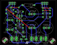
Hi Ketje, thanks for looking at that PCB layout however I'm using prototype boards so my layout follows the drawing in my first image. Is the aim of your modification to bring the 470u closer to the BD675 or to reduce the path to GND?
Cheers!
An externally hosted image should be here but it was not working when we last tested it.
Hi Ketje, thanks for looking at that PCB layout however I'm using prototype boards so my layout follows the drawing in my first image. Is the aim of your modification to bring the 470u closer to the BD675 or to reduce the path to GND?
Cheers!
Last edited:
To220, To247 and To264 are all bce
To126 are all ecb. I have never found any exceptions among lots of BJT transistors.
2sa/sc To92 are also bce, again I have not seen any exceptions.
To126 are all ecb. I have never found any exceptions among lots of BJT transistors.
2sa/sc To92 are also bce, again I have not seen any exceptions.
To220, To247 and To264 are all bce
To126 are all ecb. I have never found any exceptions among lots of BJT transistors.
2sa/sc To92 are also bce, again I have not seen any exceptions.
Yes, the mistake is in the circuit layout rather than the package pin out
Struggling for ideas here, so could the issue be with the selection of devices, specifically the gain of the BJTs?
BC560C with 110hFE
BC337 with 400hFE
BD437 with 85hFE
BD675 with 750hFE
BC560C with 110hFE
BC337 with 400hFE
BD437 with 85hFE
BD675 with 750hFE
bc560 has a specified gain range of 110 to 800.
These are subdivided into a, b & c
bc560c is 420 to 800.
If you have any C grade that measure 110, then they are either faulty, or fake.
Either use them as relay drivers or bin them.
At what Ic or Ie are you measuring the hFE?
It is specified in the datasheet.
These are subdivided into a, b & c
bc560c is 420 to 800.
If you have any C grade that measure 110, then they are either faulty, or fake.
Either use them as relay drivers or bin them.
At what Ic or Ie are you measuring the hFE?
It is specified in the datasheet.
Last edited:
Sorry I was reading the suppliers spec, which is wrong, I tested it today and the hFE is 418. So, no problem there and no solution 😡
Sorry but Red Circuits is not a reliable schematics source.
And that´s a big understatement 🙁
Unfortunately tons of beginners end up there and get attracted to the poor designs because they are usually very simple, not to mention they often promise way more than they can actually deliver.
They already deleted some gross examples such as a 10000 (or was it 20000?) W amplifier with some 20 pair power devices per side and similar stuff, but that has not improved the remaining ones.
If you like Class A, just search around in DIY Audio, you will find excellent designs, well documented, built by many, and on which you can ask help from people who successfully built them.
Yeah I had never used Red Circuits before but it was recommended to me while I was looking for a low Watt amp
I had a look around and found it to be a similar but simpler design to the DoZ on elliot sounds so went ahead with it, maybe I should have just done the elliot sounds design instead 🙄
I had a look around and found it to be a similar but simpler design to the DoZ on elliot sounds so went ahead with it, maybe I should have just done the elliot sounds design instead 🙄
Elliott designs are 120% reliable 🙂
Also the many class A designs in DIY Audio 🙂
Edit: Elliott switched servers short ago, so if your links come out empty, search again, I think he also posted the new ones here.
Also the many class A designs in DIY Audio 🙂
Edit: Elliott switched servers short ago, so if your links come out empty, search again, I think he also posted the new ones here.
To me the key thing is to play around with:
-the 100R resistor at BC560 collector to reduce the gain.
-the 680R which I believe sets the current through the BD437
-the 100R resistor at BC560 collector to reduce the gain.
-the 680R which I believe sets the current through the BD437
Yes I've done a few of Elliott's designs and been very happy but this time I wanted to try something different and this design fit the bill....
On the bright side this is forcing me to understand more of how these things work 😀
On the bright side this is forcing me to understand more of how these things work 😀
Reducing the gain of the BC560C has settled one of the amps, the other is still having some issues so it looks like one of the devices has failed🙁
Reducing the gain of the BC560C has settled one of the amps, the other is still having some issues so it looks like one of the devices has failed🙁
I have an amp I just built, Jean Hiraga Le Monstre which uses BC560C and BC550C. One channel runs fine, the other runs super hot - to the point of a bit of smoke coming off. Luckily there's plenty of heat-sinking and fan to cool the unit down, however this is a problem I can't seem to resolve.
I suspect the BC560C/550C are driving the amp too hard- perhaps failed devices, but my biasing on the amplifier seems fine. I have no idea 🙁
- Status
- Not open for further replies.
- Home
- Amplifiers
- Solid State
- Class A sinking too much current