Designing a class A SE guitar amp using a kt88. Im shooting for 15-20w. Here are my specs:
HV: 350v
Rk: 220
Ck: 1uF
Rg2: 470
Rstop: 1k
Rg1 (in series): 5k
Rgshunt: 200K pot
Transformer: SE Edcor 3K primary.
I am trying to simulate in Pspice/Multisim and I am running into parameter/convergence errors with my transformer. Anyone know how I should go about modeling a SE transformer? Also any pointers on SE design for maximum power output would be great. Thanks.
Can you post your circuit in pspice. I could try to simulate it and see if I can make heads or tails of it.
Tubelab.com has a big list of sim results on his Simple SE pages. These list power output for the usual octals at various HT, cathode resistors and 3k and 5k OPTs. All in triode mode (hi-fi).
350V HT, 220ohms on the cathode and a 3k OPT results in 3.3W triode mode. Double it for pentode mode and you are way below your goal of 15W+.
450V-500V may get you there, but don't expect long life of the KT88.
The GE datasheet of the 6550a lists a SE config that is supposed to deliver 20W (at 13%! THD,I call that clipping) 400V anode/225Vg2/-16.5V g1/3k load.
I'm more of a 'build and see' guy than running Sims 😀
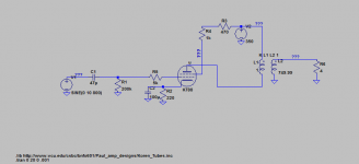
Here is the LTspice models:
I did not put in voltage and power ratings yet.
The transformer was modeled using inductors, it should give a turns ratio of about 1:27. I am modelling an Edcor CXSE25-43k.
https://edcorusa.com/cxse25-4-3k
I did not put in voltage and power ratings yet.
The transformer was modeled using inductors, it should give a turns ratio of about 1:27. I am modelling an Edcor CXSE25-43k.
https://edcorusa.com/cxse25-4-3k
Attachments
Tubelab.com has a big list of sim results on his Simple SE pages. These list power output for the usual octals at various HT, cathode resistors and 3k and 5k OPTs. All in triode mode (hi-fi).
350V HT, 220ohms on the cathode and a 3k OPT results in 3.3W triode mode. Double it for pentode mode and you are way below your goal of 15W+.
450V-500V may get you there, but don't expect long life of the KT88.
The GE datasheet of the 6550a lists a SE config that is supposed to deliver 20W (at 13%! THD,I call that clipping) 400V anode/225Vg2/-16.5V g1/3k load.
I'm more of a 'build and see' guy than running Sims 😀
Great! Ill check out tubelab.com. And I was stuck between a 6550a or KT88. I found the 20w AX84 online as a KT88 design reference. I figured simulation would at least tell me if I am way off. Which I might be now, that you mention it. Any good design rule of thumbs you guys have? I designed from the ground up thinking I would learn how these amps fully operate, only to find myself getting lost using different approaches, and making certain assumptions.

Can you post your circuit in pspice. I could try to simulate it and see if I can make heads or tails of it.
Posted the spice model hopefully you can make sense of it.
And I was stuck between a 6550a or KT88.
I got a bunch of " previously auditioned" (used returns from the Tubestore.com) EH KT88's and EH 6550's cheap, about 8 or 10 years ago. I was convinced at the time that they we the same tube. All the tubes had Tubestore "perfect pair" matching numbers on them, some were pairs, and some were singles. I found a single KT88, and a single 6550 with identical matching numbers, so I stuck them in a push pull amp, and they worked great. I have no idea if the current vintage tubes are the same.
Tubelab.com has a big list of sim results on his Simple SE pages........450V-500V may get you there, but don't expect long life of the KT88.
I stuck a pair of the EH KT88's in a Tubelab SSE which runs 430 volts at about 80mA on the KT88. About 40 volts are dropped across the cathode resistor so the tube eats 390 volts at 80 mA for 31 watts of dissipation. Those tubes are still in the amp....8 years later. It puts out 14 clean watts in UL mode for HiFi duty. OPT is 5K ohms.
I have connected an SSE in pentode mode with 460 volts of B+ (solid state rectifier) plugged my guitar preamp into it and beat the ^%*%# out of it. I was getting about 17 watts with the same 5K OPT at the onset of clipping. This was not however a long term test.
Note, a class A SE amp like an SSE or a Fender Champ, is NOT class A any longer when you plug a pedal board into it, set it on KILL, dime all the knobs and cut loose. The amp left class A as soon as you hit clipping! Tube current goes all over the place as the amp goes in and out of clipping, and the guitar speaker transitions through resonance. A 3K OPT might be a bit too hard on a KT88 with B+ over 400 volts. I prefer 5K and more voltage.....it's easier on the tube, and it just screams!
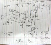
About 15 years ago I built a bunch of "Turbo Champs" no two were alike, they were made out of whatever I had at the time. Speakers ranged from a single Weber 8 inch to a pair of speakers that I pulled out of my car before trading it in. Output tubes were anything from a 6V6 to a KT88, although most were KT88's on high voltage. This schematic was drawn from memory after the fact, and may not exactly match any particular amp.
Attachments
Looking at your Turbo Champ schematic, how did your decide your value of 2K ohm + 100ohm for the maximum grid resistance?
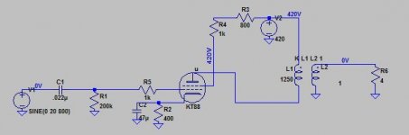
Sorry it took so long. I lost the ability to do this at home somehow, so i had to wait to come back to work and do it on lunch hour. I was able to simulate your circuit just fine, except for a couple of errors. Your transformer impedance ratio is backwards. You created a step-up transformer, not a step down. In Pspice you specify the inductance, and the datasheet says 41H for the primary, s I set the secondary to 55mH which is the 750:1 ratio. The other issue is your coupling cap of 47pF is way too small for a 220K load on the other side. I made it a 0.22uF and it works just fine. I also added the 70 ohms DC resistance he transformer datasheet says it has, but it may not matter. When things don't converge in Pspice I add small resistors or caps and try not to have pure inductors and capacitors. there is always some small amount of parasitic stuff in real circuits, and in fact in the semiconductors as well, which are usually the things that cause the non-convergence issues.
So I guess make those changes and see if your circuit starts working, or at least converging.
So I guess make those changes and see if your circuit starts working, or at least converging.
So I guess make those changes and see if your circuit starts working, or at least converging.
Multisim seemed to be the one having problems. It wants leakage inductance and magnetizing inductance as parameters for the transformer, which I don't have data for, and the circuit seemed very sensitive to. I have since updated my design in ltspice and it seems to work more accurately. According to my rough loadline calcs and simulations, I should be getting close to a grid voltage input at about 10-15 volts peak before clipping. Does this seem correct?
Based on that I would need approximately 2 AXu7 gain stages, possibly 3 depending on my tone circuit. I would also like a good amount of overdrive distortion. I am currently looking at Ax84 lead preamp circuit attached. Any thoughts? Suggestions? Criticism?

Attachments
Turbo Champ schematic, how did your decide your value of 2K ohm + 100ohm for the maximum grid resistance?
I assume that you are referring to the screen grid, it's 100 ohm resistor, and two 1K resistors on a switch. If so these were all determined by trial and error. The resistor choices depend on which output tube is being used. I have built "Champ" like amps since the 60's with all kinds of output tubes including TV sweep tubes. For this discussion we will assume commonly used output tubes.
Most of my Turbo Champs during the late 90's used early Chinese or Sovtek KT88's or 6550's. These will work with any resistor value above 100 ohms, and of course the power will go down, and distortion go up as the resistance increases. Some of the early Chinese KT88's would blow up, often violently on a B+ over 400 volts, but these are all dead by now. The resistors should be at least 2 watts.
I also used EL34's. These tubes can all be different, since the quality control as far as grid alignment is concerned varies from batch to batch. A well made EL 34 wants a 1K or higher resistor. Mis-aligned EL34's draw more screen current, and may distort too much with a 1K ,but some will melt down with smaller resistors. Don't go below 470 ohms if your B+ is over 450 volts.
Good 6L6GC's and most crummy ones will work with any resistor over 100 ohms. Chose the tone you like.
Hey Tubelab...it's been a while since I've been on here, I've been busy taking guitar & bass lessons, and building guitars. How have you been? I picked up a pair of Aguilar DB359 bass amps, one working and one not.
Besides my champ clone, I picked up somebody else's project on eBay. It uses just one 12 AX7 and one 6L6 wired as a triode. I think it has the smaller 125CSD output transformer which is probably OK for the lower triode output. I don't think it has any feedback. Haven't listened to it yet. I wonder what other output tubes I might try in there LOL.
I have enough "spare" parts to make another single-ended super-champ with two 12AX7, one KT120, and a 125 CSE. I can't remember what power transformers I have... How would you recommend I wire the screen, triode or tetrode, and do they really sound any different besides the power output difference? Should I cascode the preamp output to get enough current to drive the KT120? My B+ is probably going to be lower than it should be... Besides possibly being a waste of potential, would the KT120 make a cool "triode" for guitar? What else am I going to do with ONE KT120 anyway, it's been knocking around unused... I've got a lot of EL34 and 6L6GC take-outs too...
Last edited:
made an se "champ" for a friend to practise witch is partially based on tube labs turbo schmatic didnt hav a high voltage trany think it was round 300 b+ so only puts out about 5 watts from kt88 but he loves it allthou it brakes up a bit soon (low b+) all his friends think its cool, so thanks for the insperation tubelab.
Hey Tubelab......How have you been?
Lost my job of 41 years, packed up what I could, and left Florida. After two moves I have settled into what should be my "retirement" home in rural West Virginia. I am still building my new lab in a large empty basement, while trying to unpack and organize stuff that was thrown into boxes when I had to be out of my house with 3 weeks notice. A lot was sold, given away, or trashed in Florida before we left.
During one of those "unboxing" moments I found amp 1.4 from the Hundred Buck Amp Challenge thread. The fun starts in post #1605 of that thread. It has now evolved into an amp that I play exclusively.....OK, it's the only working amp that I have at the moment. It does sound good though. I'm still looking for Amp 2.whatever. That one screamed.
How would you recommend I wire the screen, triode or tetrode, and do they really sound any different besides the power output difference?
The second biggest difference between triode and pentode wiring is output impedance. A triode without feedback has a relatively low output impedance. This controls the cone motion in the speaker, and usually leads to "tight" sounding bass. It will lessen the speakers contribution to the amps overall tone. A pentode, especially with zero, or minimal feedback, has a much higher output impedance. This leads to uncontrolled cone movement, and the speaker becomes an integral component of the amps behavior especially when the speakers resonance falls within the guitars frequency range. This is why guitar amps tend to use smaller coupling caps that an equivalent HiFi amp.
I tend to prefer a pentode for lead guitar, but a triode may work well for rhythm or clean lead tones.
the KT120?
I have never seen the KT120 or KT150 since they are beyond my price range. I would assume that they behave like a bigger KT88.
I have not found the need to use mosfet drive or any higher current drive for KT88's, but I don't know the behavior of the KT120 in the near zero bias region. One must be careful with any low impedance drive scheme if the amp will be driven to clipping a lot, and the grid of the output tube is fed through a capacitor. This can cause bias shift, and possible blocking distortion "farting out." The usual means of controlling this are a smallish coupling capacitor, and a larger than normal grid stopper resistor.
The grid circuit resistance requirement of the KT120, and Miller capacitance in triode mode, may be issues that force the use of a higher current driver.
I used the 125CSE in several of my Turbo Champs, and I thought that it was near the end of its DC current spec with a KT88. My guess is that the KT120 may want more current that the CSE can eat.
Bummer about your job. The mainframe software business kicked my butt in Cali during the recession. They're just not making much new mainframe software. I ended up contracting, without health insurance, and struggling to keep my house. Too many delays funding new contracts. I ended up keeping my house, but not being able to afford to live in it. Somebody else rents it from me, I lose money on it every month, and got a new 40-year mortgage so I'll own it 10 years after I'm dead. A great company paid to relocate me to Virginia but I too had to sell a lot, gave away my grandfather's piano.
KT120 is a KT88 and a half, mostly just just longer elements. Well, a little less than that... More filament current, more capacitance. more output current, a little harder to drive.
Now I'm renting a basement. Houses here near Washington DC are outrageously expensive, they make Cailfornia look cheap. Don't really have a decent bench set up.
Bummer about your job.
It sucks, but I lasted 41 years in the same place. Like who does that any more. I got a letter from the CEO explaining that I was part of a "target group" that was selected to receive a buyout offer, I took it. Those who didn't and enough others to avoid "age discrimination" were laid off shortly after the deadline for volunteering had passed. Oddly enough, I was given two employment extensions so that I could finish the projects of two guys that were laid off.
Shortly after I left the company cancelled the retiree health care plan that was promised. There is only one Obamacare provider in this state. They suck, and charge us $1800 per month. The subsidy cuts that in half, but prevents me from taking a job, unless it offers health care.....isn't going to happen, since there are zero high tech jobs here, and none of the stuff I did in the last 20 years exists in the US anymore. The budget for experiments is virtually zero for the next three years, until I can get Social Security and Medicare.
I sold a working but real ugly Bandmaster for $200 including the speaker cabinet which contained Radio Shack speakers.
I gave away my favorite amp, and old "Ultraflex" made by the "Audio Crafters Guild." The same amp was sold as a Magnatone, and a "Panaramic." Also somewhat ugly. I was walking a flea market in the ghetto area of Ft. Lauderdale when I spotted this Jamaican guy trying to sell the amp for $50. "It work, mon, it work" I offered $25, which was refused, and walked on.........A couple of hours later I bought the amp for $35. I had worked in a TV repair shop in Miami. I learned to take something like that home, and open it up outside armed with a can of Raid and a Shop Vac.
Upon opening it up, I found a pristine original amp with all matching Sylvania tubes, including 4 X 7355's. Those alone were worth the $35. I stood back, and plugged it in.....It did work, mon. I never touched the amp, just turned it on and played. It never missed a beat in 15 years. The guy I gave it to used to be a regular here. He had one like it but never got around to fixing his. He showed up to pick up several hundred pounds of transformers, and a car full of tubes when he saw it. He really didn't believe it when I told him the story, so I turned it on.......
Update To Design, Question on Tone Stack
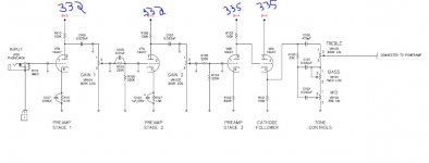
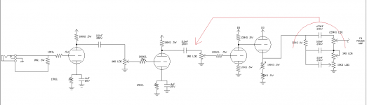
attached is my preamp design. The preamp is somewhere between an AX84 Lead Preamp, and a Medium/High Gain circuit from "Designing Valve Preamps for Guitar and Bass" by Merlin Blencowe. Tone stack is voiced as a Marshall. My question is to why they have their tone stacks at the end of the of the preamp rather than in the middle like a Champ style amp. I have various 100V poly caps I would like to use where possible.
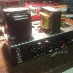
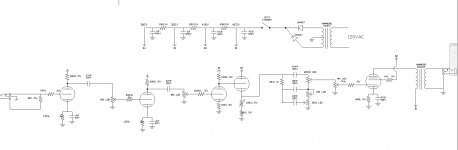
Also attached is the complete tube circuit, and a picture of the chassis build. This amp will be microcontroller integrated for DSP effects. Bifet preamp boosts and clamps to 2.5volts bias for ADC microcontroller input. Also has 5.1 zeners for protection (although this may cause aliasing and I may just reduce the gain a bit and remove them, havent tested yet) Also a Bifet mixer for microcontroller DAC output and guitar signal, Bypass controllable via a 5V signal relay. Will upload digital schematics if anyone is interested.
Thanks!
attached is my preamp design. The preamp is somewhere between an AX84 Lead Preamp, and a Medium/High Gain circuit from "Designing Valve Preamps for Guitar and Bass" by Merlin Blencowe. Tone stack is voiced as a Marshall. My question is to why they have their tone stacks at the end of the of the preamp rather than in the middle like a Champ style amp. I have various 100V poly caps I would like to use where possible.
Also attached is the complete tube circuit, and a picture of the chassis build. This amp will be microcontroller integrated for DSP effects. Bifet preamp boosts and clamps to 2.5volts bias for ADC microcontroller input. Also has 5.1 zeners for protection (although this may cause aliasing and I may just reduce the gain a bit and remove them, havent tested yet) Also a Bifet mixer for microcontroller DAC output and guitar signal, Bypass controllable via a 5V signal relay. Will upload digital schematics if anyone is interested.
Thanks!
Attachments
- Status
- Not open for further replies.
- Home
- Live Sound
- Instruments and Amps
- Class A SE Guitar Amp Design