wg_ski... thanks for that;That would be a class TD amplifier - already been done, at least for normal AB type operation. There isn’t any reason the amp couldn’t be biased into class A, other than the dissipation issues. The down converters on the power supplies do create digital noise which is impossible to completely eliminate, and do have a finite response time. The finite response time when running in class A would still necessitate a high SOA in the output stage to deal with the occasional high peak dissipation, but at least the average thermal load heating up the house would be less.
Some of the cheap clones of the well respected brands like Labgruppen are pretty rough - full of easily audible digital hash and stair step looking waveforms. Only really suitable for subwoofers. But that’s not an intrinsic limitation - just what happens when someone clones a circuit they don‘t understand.
If it can be properly designed and implemented, i really think Class TD is the ultimate approach.
Idea: Design a Stand alone power supply that is fed an analog signal and outputs an ADJUSTABLE dc voltage in real time (with crazy stupid fast slew rate) and high current on tap.
The design would have min_max voltage levels but not STEP voltages but rather a RAMP thereby, i think, minimizing switching noise. So essentially a less square but more triangular shape transitioning to a trapezoid.
You can then choose your amplier topology independently, regardless of class, A, AB etc or type bjt, fet, tube...
anyone knowing of anything out there like that?
Years in fhe field... elevator music to multi10kw pa systems ..Possibly a Silly suggestion
BUT wouldn't a More Direct path be; Buy /Use higher efficiency Speakers?
Which don't Need high power to sound good?
you need two things besides fidelity
1..CURRENT for that iron fisted grip on speaker motion.. and
2.. Voltage for excursion...ie volume level
In any home indoor listening setting i believe around 40V rms into any load...is just about enough to achieve "live listening" levels... but you can never have "too much" current... so im sorry to tell you but you'll need power -lots of it- to achieve live listening levels... unless you only listen to flute music...
go listen to a drum set going full bore live or a church choir of 50+ people ...then go ahead and try to replay that on speakers at home....then youll understand
Look at this thread. https://www.diyaudio.com/community/threads/200w-class-a-amp-with-high-efficency.304722/#post-5008854
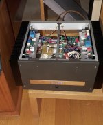
I have all ready to test it but somehow was occupied with other projects, like one similar to this one but simpler and here is the photo of the working prototype 100W ClassA + ClassB.
I have all ready to test it but somehow was occupied with other projects, like one similar to this one but simpler and here is the photo of the working prototype 100W ClassA + ClassB.
Attachments

You may be confusing class H with TD. TD is continuously variable, using a switching buck converter in the supply. Some implementations are so horrible that stepped class H would have been better. The approach used in the Yamaha EEEngine works well, but only for relatively light duty use. It is VERY clean, but if you were going to bias the amplifier core into class A there are things about it that would need attention in order to take the “abuse”. The slew rate of the EEEngine is limited, so power dissipation rises when the audio frequency you’re reproducing goes above a few kHz. In practice, that doesn’t hurt anything because most of the energy is in lower frequencies. If you bias into class A, power dissipation will rise anyway, so you need a bigger heat sink than they use with the class AB core. It will still be smaller than an equivalent ordinary class AB amp. Since your peak dissipations will be high, you need to go back to the 6 to 10 power transistors in parallel you would normally use in a standard amp. For other reasons, you would need to raise the buck converter switching frequency. There are no hard road blocks preventing you from doing any of this, other than cost and development time. There is no need in the commercial marketplace, so you’d be on your own going this far off the reservation. Not something you can just clone without doing your homework.wg_ski... thanks for that;
If it can be properly designed and implemented, i really think Class TD is the ultimate approach.
Idea: Design a Stand alone power supply that is fed an analog signal and outputs an ADJUSTABLE dc voltage in real time (with crazy stupid fast slew rate) and high current on tap.
The design would have min_max voltage levels but not STEP voltages but rather a RAMP thereby, i think, minimizing switching noise. So essentially a less square but more triangular shape transitioning to a trapezoid.
You can then choose your amplier topology independently, regardless of class, A, AB etc or type bjt, fet, tube...
anyone knowing of anything out there like that?
In theory, the approach does not have the switching noise associated with class G or H. There is ALWAYS crossover distortion that occurs when the rails switch with those approaches. Biasing the core into class A can eliminate the distortion notch at the zero crossing, but not when the rails switch. In practice, the latter is almost always inaudible, but it can be observed. EEEngine is free of this, but NO high frequency switching circuit is free of radiated and conducted EMI. The levels can be made low with proper attention to EVERYTHING. But the more current you draw the harder it is to suppress, and class A bias will make you draw lots of current. Things you don’t even have to think about when you’re cloning an old Pass Labs amp will drive you up the wall here. Sure you can get it cleaned up. It will take money and time. It’s your money, and it’s your time. This isn’t to discourage anyone - but you do need to know what you're up against.
i love it... i absolutely love it ..
the challenges AND the ingenuity required to bypass these obstacles...
i will respond thus:
1... nope not confusing H for TD... ive used H for crazy high voltages like 120V+ just for SOA on output transistors and its a godsend in those cases
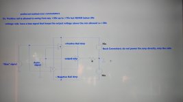
2.... Yes TD is basically a single rail amplifier that is not allowed to "crossover" below the min voltage output... that is the difficulty right there of controlling that beast... then that out put drives one of the rails of a normal amp...so you need two ..one for each rail
applications... i believe that is the A plus D versions ive been hearing about
see concept diagram 1
3.... i believe if the voltage level is kept very low then current draw at either idle or full ouput will not really be an obstacle . You need both power and current to produce heat so if you up the current to lets say 5 amps but at 3 volts... your output devices are being asked to dissipate 15watts...
then as needs arise (musical signals) then you got that voltage swing to go with it .
The A+D method is very attractive because there is literally no stepping of any sort, you have an analog signal from the rails (pseudo DC) used as a power source for another amp (output amp)... is this the way Lapgruppen does it?
4... yes.. using a buck converter - to power the amp directly ( or any switching mechanism whatsoever) will produce the nasties..🤔
its a welcomed head ache...😎😅
5...why am i discussing this idea with ya'll...? ans: to get all of the unseen out of the way to know exactly what im up against
6... there may be a solution.. another type and rather attractive and INGENIOUS has Mr.Pass remarked...
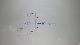
that one provided by Sona, one floating high current low voltage amp being driven by another lower current higher voltage amp...see dia 2
7.. i drawing up method two as i write this..
the challenges AND the ingenuity required to bypass these obstacles...
i will respond thus:
1... nope not confusing H for TD... ive used H for crazy high voltages like 120V+ just for SOA on output transistors and its a godsend in those cases
2.... Yes TD is basically a single rail amplifier that is not allowed to "crossover" below the min voltage output... that is the difficulty right there of controlling that beast... then that out put drives one of the rails of a normal amp...so you need two ..one for each rail
applications... i believe that is the A plus D versions ive been hearing about
see concept diagram 1
3.... i believe if the voltage level is kept very low then current draw at either idle or full ouput will not really be an obstacle . You need both power and current to produce heat so if you up the current to lets say 5 amps but at 3 volts... your output devices are being asked to dissipate 15watts...
then as needs arise (musical signals) then you got that voltage swing to go with it .
The A+D method is very attractive because there is literally no stepping of any sort, you have an analog signal from the rails (pseudo DC) used as a power source for another amp (output amp)... is this the way Lapgruppen does it?
4... yes.. using a buck converter - to power the amp directly ( or any switching mechanism whatsoever) will produce the nasties..🤔
its a welcomed head ache...😎😅
5...why am i discussing this idea with ya'll...? ans: to get all of the unseen out of the way to know exactly what im up against
6... there may be a solution.. another type and rather attractive and INGENIOUS has Mr.Pass remarked...
that one provided by Sona, one floating high current low voltage amp being driven by another lower current higher voltage amp...see dia 2
7.. i drawing up method two as i write this..
Attachments
yes....thats exactly my thoughts also. NICE IDEA indeedOne idea could be to vary the rail voltages, a la buck converters with a duty cycle that increases when a certain threshold is exceeded.
Ideally, the PSU would be smoothly ramped up in anticipation of an upcoming peak in the analogue signal path. A nice idea for digital audio. Although I guess a "true analogue" amplifier could be also based on modulating and filtering a voltage source to produce an audio signal. It doesn't always have to be either switching XOR linear.
Mr Pass pointed me to the SANO patent which is exact y what you're proposing here.. i believe this will work..Look at this thread. https://www.diyaudio.com/community/threads/200w-class-a-amp-with-high-efficency.304722/#post-5008854
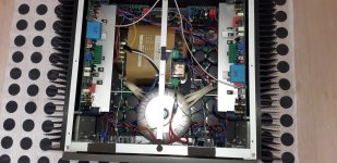
I have all ready to test it but somehow was occupied with other projects, like one similar to this one but simpler and here is the photo of the working prototype 100W ClassA + ClassB.
kudos bro... if you may, please keep me up to date on the results...😎
Another variation:
Full bridge. 1st half-bridge is class A.
The 2nd half-bridge is fed a modified audio signal producing a low noise virtual ground most of the time, except for peaks "above clipping" (class C?).
Another thing to consider could be glitches in the output resistance.
Or class D with more MOSFETs and rail voltages. The switching scheme could smooth out the transition regions, like DACs use dithering to reduce quantization noise.
Ideas are cheap. It's the implementation and finishing touches that can be a challenge.
Devialet?A few years back there was a company that released a large globe shaped speaker with the claim it produced high power with distortion free output. The amp for the bass driver was class A with the power rails derived from two tracking class D amplifiers. I can't remember the name of the company but this paper from 2004 touches on the principal. http://hdl.handle.net/1721.1/28384
https://www.devialet.com/en-us/phantom-speaker/phantom-i/
i
im attempting the SANO patent solution... it looks promising so farAnother variation:
Full bridge. 1st half-bridge is class A.
The 2nd half-bridge is fed a modified audio signal producing a low noise virtual ground most of the time, except for peaks "above clipping" (class C?).
Another thing to consider could be glitches in the output resistance.
Or class D with more MOSFETs and rail voltages. The switching scheme could smooth out the transition regions, like DACs use dithering to reduce quantization noise.
Ideas are cheap. It's the implementation and finishing touches that can be a chal
Those are they.
Lo and behold...🤭i love it... i absolutely love it ..
the challenges AND the ingenuity required to bypass these obstacles...
i will respond thus:
1... nope not confusing H for TD... ive used H for crazy high voltages like 120V+ just for SOA on output transistors and its a godsend in those cases
2.... Yes TD is basically a single rail amplifier that is not allowed to "crossover" below the min voltage output... that is the difficulty right there of controlling that beast... then that out put drives one of the rails of a normal amp...so you need two ..one for each rail
applications... i believe that is the A plus D versions ive been hearing about
see concept diagram 1
3.... i believe if the voltage level is kept very low then current draw at either idle or full ouput will not really be an obstacle . You need both power and current to produce heat so if you up the current to lets say 5 amps but at 3 volts... your output devices are being asked to dissipate 15watts...
then as needs arise (musical signals) then you got that voltage swing to go with it .
The A+D method is very attractive because there is literally no stepping of any sort, you have an analog signal from the rails (pseudo DC) used as a power source for another amp (output amp)... is this the way Lapgruppen does it?
4... yes.. using a buck converter - to power the amp directly ( or any switching mechanism whatsoever) will produce the nasties..🤔
its a welcomed head ache...😎😅
5...why am i discussing this idea with ya'll...? ans: to get all of the unseen out of the way to know exactly what im up against
6... there may be a solution.. another type and rather attractive and INGENIOUS has Mr.Pass remarked...
that one provided by Sona, one floating high current low voltage amp being driven by another lower current higher voltage amp...see dia 2
7.. i drawing up method two as i write this..
i was looking at some carver schematics and came across the schematic for one of his powered subs...
Lo and behold... it uses the EXACT scheme pictured here...down to the bias signal to achieve the starting voltage point... 🤓 and i guess our switching artiifcacts become more or less irrelevant at bass frequencies so this scheme is very well suited for controlling dissipation in high powered subs... the rails were +/- 120v !!!! now thats HIGH power.
That guy is a genius..
Long live Bob Carver.
Attachments

- Home
- Amplifiers
- Solid State
- Class A amp with dual Linear supply