MF 12 Complementary shematic at Pass DIY
Desmond Harrington has add the MF 12 complementary version schematic to the Mosfet Citation 12 PDF file.
Brian
Desmond Harrington has add the MF 12 complementary version schematic to the Mosfet Citation 12 PDF file.
Brian
Productive engineers hate to "reinvent the wheel". That's probably why the original Citation 12 circuit was lifted from the RCA transistor manual, circa 1969 (leaving out the protection circuit, but essentially cloning the design even to the parts values). RCA wanted to sell transistors, so they gave away well-proven designs in hopes that engineers would take them as-is, and design in RCA parts. Sure enough, the output transistors in the Citation were RCAs.
Fast forward 10 years, power MOSFETs have become a commercial reality and International Rectifier, a major MOSFET maker, publishes an application note to sell transistors into the audio market. The design bears a stunning resemblence to the old RCA designs. And why not? The core concept was already well-proven and familiar to most audio engineers.
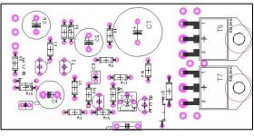
The reason I mention this is that the IR app note is still available, online and the design is quite similar to the MF12. If you are doing a new implementation, you might want to leverage the IR PCB design. The application note contains PC board artwork with parts values and is available at:
http://www.irf.com/technical-info/an948/an-948p1.htm
The app note recommends some available MOSFETs, IRF53X and -953X, but I would suggest using higher current parts such as the IRF540/9540s. Those have twice the dissipation and current ratings of the IRF130/9130, which are obsolete anyway.
There are some important improvements in the Pass MF12 design: feedforward compensation via capacitor C3, and resultant elimination of the output inductor. Feedforward has been used for a long time for opamp compensation and is also used in the Leach amp, another well-proven design. It really does seem to work well here, allowing a slew rate speedup while maintaining stability. It's also great to eliminate the output inductor, although I confess I want to see this proven on tough real world loads, such as electrostatics.
I would suggest adding a catch diode on the gate to the upper N-channel MOSFET, because there is risk of exceeding the 20 volt gate/source voltage limit and also because it makes the clipping behavior more symmetric. Without it, on large amplitude high frequency tone bursts there is a slow recovery from saturation on the top side, and that sort of behavior indicates possible problems with recovery from overloads. (It was called D3 in the original QC MF-12, and perhaps it should be retained and be a fast diode like a 1N4148).
Overall I like the design for its simplicity. It's a pretty good performance kicker for an old design. Well, you should just build it and hear for yourself.
Fast forward 10 years, power MOSFETs have become a commercial reality and International Rectifier, a major MOSFET maker, publishes an application note to sell transistors into the audio market. The design bears a stunning resemblence to the old RCA designs. And why not? The core concept was already well-proven and familiar to most audio engineers.
The reason I mention this is that the IR app note is still available, online and the design is quite similar to the MF12. If you are doing a new implementation, you might want to leverage the IR PCB design. The application note contains PC board artwork with parts values and is available at:
http://www.irf.com/technical-info/an948/an-948p1.htm
The app note recommends some available MOSFETs, IRF53X and -953X, but I would suggest using higher current parts such as the IRF540/9540s. Those have twice the dissipation and current ratings of the IRF130/9130, which are obsolete anyway.
There are some important improvements in the Pass MF12 design: feedforward compensation via capacitor C3, and resultant elimination of the output inductor. Feedforward has been used for a long time for opamp compensation and is also used in the Leach amp, another well-proven design. It really does seem to work well here, allowing a slew rate speedup while maintaining stability. It's also great to eliminate the output inductor, although I confess I want to see this proven on tough real world loads, such as electrostatics.
I would suggest adding a catch diode on the gate to the upper N-channel MOSFET, because there is risk of exceeding the 20 volt gate/source voltage limit and also because it makes the clipping behavior more symmetric. Without it, on large amplitude high frequency tone bursts there is a slow recovery from saturation on the top side, and that sort of behavior indicates possible problems with recovery from overloads. (It was called D3 in the original QC MF-12, and perhaps it should be retained and be a fast diode like a 1N4148).
Overall I like the design for its simplicity. It's a pretty good performance kicker for an old design. Well, you should just build it and hear for yourself.
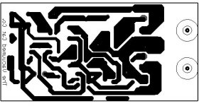
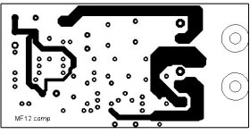
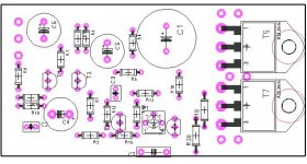
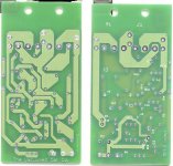
Boards complementary mf12
New Boards in, one pair in the mail to Brian.
Referring to a bit of turmoil in the Zen v5 thread i would like to clarify:
I am aware of mr Pass IP in this design, althoug it originates in an HK design taken straight out of RCA´s transistor handbook.
I believe Passdiy do not supply boards for this design so there would be no conflict.
Theese boards are available for Diyérs who would like to use professional quality plated throug boards. Boards are 70u cu.
I´ve no comercial interest in this, i´ve paid 60 SEK per board, roughly 8 US. I´ll send a pair to anyone interested, if receiver wish i´ts ok to send reimbursement, or something fun.
Attachments
I am very interested in this citation 12 mosfet project,
the links iin that last post are broken or something.
the links iin that last post are broken or something.
Forgotten promisses
Finaly sorting out most of the mess after my computers were
stolen this summer. Unfortunately a lot of stuff was only saved locally, among others a lot of mail.
So asking if there still are anyone out there whom i´ve
promissed boards for the mosfet Citation but still has´nt received any, please let me know.
Ingvar
The complementary version of the HK12 was just a quickie,
and if you want a really low parts count HK12, that sounds
like fun. 😎
and if you want a really low parts count HK12, that sounds
like fun. 😎
Original or complementary
Questions regarding which model to build, original or complementary, keeps coming up. As i´ve built and used both types my thoughts are: Given the same supply, up to +/- 50V
rails and biased up to 1A per output device it´s very hard to hear any difference at all. The complementary is simpler and, using my boards theese are better than the original type, so that is the best option for most cases. If You want to crank the bias up towards 2A or more per device stick to original version as
complementary pairs taking that much abuse are scarce.
Using it that way on the other hand is fun as both low level resolution and bottom end power seems to improve, take care thou, under theese conditions, 2,5A 50V per IRFP264 it once in a while turns into a smoke generator.
Semiconductor alternatives
Another question still coming up is availability of the input and driver transistors. Talking to You building this amp in USA, Canada, Australia, Holland, Hong Kong, Norway, Sweden and probably more places too, it´s obvious that availability differs a lot between markets. Biggest problem is always 2SA872A for input pair, sometimes You find and order some and recieve 2SA872 which is only usable with rails below 40V. One good alternative is 2SA970 often used in higher quality japanese amps so it should be obtainable from better sparepartsuppliers globaly.
The Zetex driver transistors should be less of a problem. There are ofcourse several good alternatives so if You tried anything that worked out good, please post here so we can put a good crossreference list together. Also, those still waiting for 2SA872A pairs frome me, pls give me a note.
Hi!
Inspired by these discussion I made a small single sided PCB layout for MF12. You may download the layout from:
http://www.diyaudio.com/forums/showthread.php?s=&threadid=134&highlight=citation+12
Rajeev: Sorry for late reply Ciation 12 mosfet version can be found at PASS site under legacy section.
I am using IRFP250 with source resistors and the amp indeed sounds great. As for higher rail losses, for now I can live with it considering the simplicity of PASS design.
Thankyou Mr Pass.
Regards
Rahul
I once made a couple of amps following the Citation 12 Mosfet version schematic, and they worked pretty good until they failed with no apparent reason.
I used IRFP150 and was told that the higher transconductance vs the original mosfets could have caused the problem... can anyone elaborate on this?
Cheers
Andrea
I used IRFP150 and was told that the higher transconductance vs the original mosfets could have caused the problem... can anyone elaborate on this?
Cheers
Andrea
Hi Andrea
The irfp150 should work well but can be close to absolute max ratings on a +/- 50V supply, a good type to use is irfp 264.
The only way any of my mf12 amps has ever failed was caused by driver stage transistors not handling rail to rail voltage or, a couple of times, overentusiastic bias current setting >2,5A.I once made a couple of amps following the Citation 12 Mosfet version schematic, and they worked pretty good until they failed with no apparent reason.
The irfp150 should work well but can be close to absolute max ratings on a +/- 50V supply, a good type to use is irfp 264.
The power supply was about +/- 35V so I don't think it was a problem of too high supply rails...
Cheers
Andrea
Cheers
Andrea
Andypairo said:I once made a couple of amps following the Citation 12 Mosfet version schematic, and they worked pretty good until they failed with no apparent reason.
I used IRFP150 and was told that the higher transconductance vs the original mosfets could have caused the problem... can anyone elaborate on this?
I would be surprised if the use of an IRF150 would make the
difference, as it is quite rugged and should be sitting within
its ratings. Accidental overbias is a possibiity, but sometimes
things just fail for no apparent reason.
Mosfet Gates can be damaged by static voltages in handling,
sometimes causing microscopic damage whose area grows
over a period of time causing overall failure on the chip. IR
indicates that a 96 hour burn in is proof against that, and in
my production experience, 24 hours will catch virtually all of them.
Add to that the observation that with the big power chips it
really takes a more sizeable zap than with the tiny ones due
to its higher input capacitance, so they are more immune that
you might imagine. We don't really see it that often, and in my
workshop I take only the most mundane precautions.
😎
Nelson Pass said:
I would be surprised if the use of an IRF150 would make the
difference, as it is quite rugged and should be sitting within
its ratings. Accidental overbias is a possibiity, but sometimes
things just fail for no apparent reason.
😎
Actually these Mosfets were all from the same supplier... maybe they weren't properly handled.

Well... it seems that I have to dig out the boards again and try with surely healthy mosfets..
 my wife will love that
Cheers
Andrea
- Status
- Not open for further replies.
- Home
- Amplifiers
- Pass Labs
- Citation12 repair!!