Hi Terry,
I agree with your idea about trying low 1/f noise transistor for the XO. That’s why I’m going to try the FMMT617 from Zetex (it’s proved to be of very low noise in the past – due to its low Re?).
Do you have any idea of the Toshiba Part#. Toshiba has in the past proved not to be so easy to get samples from.
Still will need good Buffer Amp –any ideas – pointers – CIRCUITS! Anyone?
For my Reference board I’m going to do the Reference PWM latching in PECL – so will need a good PECL buffer / amp for the Clock. Also, does anyone have any ideas about a good PECL to CMOS Translator (5V +/- say 50mA)? The off-the-shelf parts seem to have very poor jitter specs – and are TTL output levels. I good discrete circuit would be a great help!
Hi John,
could you elaborate a little about your measurement technique? Do you use spectrum analyser (Rohde-Schwarz logo on picture) or digital scope (FFT term describing picture)?
If you use spectrum analyzer, then maybe your resolution bandwdth is set to high (width of the 1kHz test signal is almost the same as LF noise you seem to measure). Have you tried measuring with lower frequency span (200Hz) and resolution bandwidth (1 or 10Hz)?
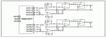
How do you measure PWM output? Do you measure outputs directly or through low pass filter as in M65817AFP data sheet?
BTW, here is the patent that describes TI principle of PCM to PWM conversion. It is mostly a feedforward system.
On related basis, have you measured new TI TAS5076 6channel PWM modulator? It has lower distortion than TAS5015 (0.005% vs 0.01%) but slightly higher noise floor (105dB in actual circuit with output stage vs 112dB for modulator only). It has internal PLL for clock generation and also 256 step gain control. I intend to try one in multiphase amplifier (use all 6 channels to amplify mono signal).
Best regards,
Jaka Racman
could you elaborate a little about your measurement technique? Do you use spectrum analyser (Rohde-Schwarz logo on picture) or digital scope (FFT term describing picture)?
If you use spectrum analyzer, then maybe your resolution bandwdth is set to high (width of the 1kHz test signal is almost the same as LF noise you seem to measure). Have you tried measuring with lower frequency span (200Hz) and resolution bandwidth (1 or 10Hz)?
How do you measure PWM output? Do you measure outputs directly or through low pass filter as in M65817AFP data sheet?
BTW, here is the patent that describes TI principle of PCM to PWM conversion. It is mostly a feedforward system.
On related basis, have you measured new TI TAS5076 6channel PWM modulator? It has lower distortion than TAS5015 (0.005% vs 0.01%) but slightly higher noise floor (105dB in actual circuit with output stage vs 112dB for modulator only). It has internal PLL for clock generation and also 256 step gain control. I intend to try one in multiphase amplifier (use all 6 channels to amplify mono signal).
Best regards,
Jaka Racman
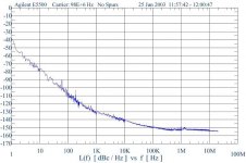
The measurements where performed using an R&S UPD5 Audio Analyser in 16K FFT mode, which results in a FFT Bin size of 2.93Hz. In this mode, the noise floor of the analyser is about –155dB (Ref to full scale 0dB input). The Zetex measurements are analyser Noise Floor limited at lower frequencies.
The outputs of both modulators have been re-latched to an External Master Clock, 2048Fs for TI and 768Fs for Zetex. The outputs from the latches are then buffered and LPF - then feed balanced to the UPD.
Despite the LPF, both the UPD and Audio Precision system II’s have a great deal of problem with “RF noisy” input signals – this is reason I posted the Thread “AES17 filter schematic” asking for circuit diagrams.
Audio Precision sells an AES17 filter set – for around $1700! I have there AUX-0025 Switching Amplifier Measurement filter, but this is only of limited use without the AES17 filters, as it only really start to work above 200KHz and is designed for sub 2Ohm input impenaces – from Output stages.
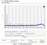
With the Re-latched TI5015, I already achieve THD @ 1KHz of 0.0002% at 0dB see FFT below - Ref. 0dB (the fundamental is notched by about 30dB by the UPD). The higher noise floor on this 0dB FFT compared to the earlier –60dB is due to the UPD.
The outputs of both modulators have been re-latched to an External Master Clock, 2048Fs for TI and 768Fs for Zetex. The outputs from the latches are then buffered and LPF - then feed balanced to the UPD.
Despite the LPF, both the UPD and Audio Precision system II’s have a great deal of problem with “RF noisy” input signals – this is reason I posted the Thread “AES17 filter schematic” asking for circuit diagrams.
Audio Precision sells an AES17 filter set – for around $1700! I have there AUX-0025 Switching Amplifier Measurement filter, but this is only of limited use without the AES17 filters, as it only really start to work above 200KHz and is designed for sub 2Ohm input impenaces – from Output stages.
With the Re-latched TI5015, I already achieve THD @ 1KHz of 0.0002% at 0dB see FFT below - Ref. 0dB (the fundamental is notched by about 30dB by the UPD). The higher noise floor on this 0dB FFT compared to the earlier –60dB is due to the UPD.
Attachments

Hi John,
If residual response of your setup (with no signal at input) does not show any LF noise then I can only help by posting link to Tripath Application note 4 that has schematics for low pass filter they use when evaluating their designs.
Alternatively, this is the picture of filter used by Renesas when characterizing M65817AFP.
Best regards,
Jaka Racman
Attachments
Originally posted by JohnW
Still will need good Buffer Amp –any ideas – pointers – CIRCUITS! Anyone?
From another of your posts
I’ve been looking at the Specs of the MC10ELT21, the Motorola Data sheet states a Fmax of 100MHz and a RMS jitter value of 35pS which seems very poor for an ECL device.
In the Analog Devices Data sheet AN-419, I wonder how much of the 110dBc / Hz phase noise is due to the MC10ELT21. It well not help that the MC10ELT21 is operating 25% faster then the Data Sheet Fmax – you can be sure that its Jitter performance will be even worst!
If memory serves, Matthys gives some buffer amps examples in his book, particularly for the EC XO I've mentionned, mainly one-stage BJT buffers/amps. Unable to re-find the xeroxed pages I've made from this, but still searching in my mess, and I'll try to post is ASA I can.
And I wasn't aware (too quick and lazy thinking...) of these figures for the PECL chip... Thanks. So, still looking for the holy Grail...
Hi All,
Thanks for the latest information. I have characterized the CXD9634 / M65817 under the same conditions as the TI / Zetex. It’s a good modulator, better then the Zetex, but not quite as good as the TI. It has a THD @ 0dB of 0.00037% and an Awtd DR of 117dB. It has a very good –30dB THD result of 0.0008%. 19Khz / 20KHz IMD 3rd order is poorer then the TI @ about –85dB (sorry for the earlier result of –105dB).
One thing to note, if used in default power up mode (no Micro) then the gain is set to –5dB. I found no mention of this in the data sheet. I also used AC dither “A” as the others had an impact on SNR. I also found it to be the best in THD terms – but I didn’t check the IMD results….
The filter schematic shown is from the Mitsubishi data sheet, shame they don’t publish component values or any frequency response curves.
As to the Clock circuit, as I’ve said earlier I’m going to us PECL for the Reference latches and Clock distribution (for these Latches).
I’m have a hard time to find a Low jitter / Phase Noise PECL to CMOS level shifter. The only device which has publish Jitter specs is the Motorola @ 35pS RMS – with this kind of performance its not worth going to PECL! Also the Motorola part has TTL output level outputs, this seems inherent to the Bi-Polar process used.
Motorola must have been trying REALLY hard to get such POOR Phase Noise figures from a PECL device!
So, I’m searching for single 5V PECL to CMOS Translator with Low Phase noise 5V output swings – does anyone have any ideas or solutions?
ICS used to make a part that would have been perfect, called the ICS508– but they have since discontinued the device – lack of demand!
Arizona Microtek make a Dual Translator, the AZ100ELT23, but the is made on a CMOS process, and they don’t publish Jitter specs.
For the Crystal SE CMOS output buffer you could use the PLL130-07 from PLL PhaseLink Corporation. This is a 100mV input Min to CMOS output buffer - but again they don’t publish Phase Noise Specs.
Found a device that looks promising, the P661 Family from PhaseLink Corporation. It has a phase jitter of <0.25pS (12KHz to 20MHz) & an RMS period jitter of <2pS (less then 1 AC logic gate!)
Spoke with the designer tonight, and we believe that there’s a fair chance of reducing the 10Hz Phase noise. Possible contribution to the phase plot could be from the RF Synthesizer used in the test set-up (very likely) and the PSU (also very likely).
Also an option to use a 5th overtone Crystal with its sharper Q.
If this device performance can be improved at 10Hz, then it looks like the ideal device as it easily meets my budget targets, and comes in CMOS and PECL flavours.
Anyone able to beat this?
Below the Phase Plot of the P661 @ 98MHz
Attachments
Hi John,
I am sorry I can't help otherwise, but there is a picture from TAS5076-5182 Evaluation Board Application Report . As you can see, they show no LF noise, and the same is with all the measurements that TI posted in their literature for other modulators. They use off board clock in their evaluation module, multiplied by internal PLL. They seem to use "TI Input PC-Board" (no specification given) as clock source. As they seem to measure 20Hz-20kHz, does that mean that your noise is below 20Hz?
Could you answer two more questions? I am aware od NDA, but is mentioned modulator by any chance TAS5508 ?
Second, is performance of TAS5015 affected by input Fs? I know it does internal oversampling, but since I will use external sample rate converter, is it better to do oversampling to 192kHz in SRC4192 or internally?
Best regards,
Jaka Racman
Attachments
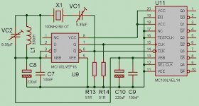
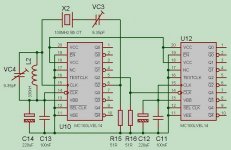
Unless I can find better, this is the circuit I plan to use for the first version of my 100MHz CLK (as I don’t expect to see Matthys book for at least a week). Its based on a circuit from Euroquartz – App note “Oscillator Circuits”
The newer Motorola PECL families claim typical cycle - cycle jitter of 0.2pS. I have no idea what this equates to in PK-PK RMS terms?
I’ve connected both VBB's together, in the hope of making any noise on these internal Ref. Nodes Common-Mode. Until I construct the Oscillator, I have no idea if this a good idea, and what the noise the Noise Spectrum looks like.
It based upon a standard Pierce Oscillator. Its claim that because neither side of the Crystal is referenced to Ground, that the Pierce Oscillator has higher Phase Noise then other Oscillator types (SaRonix App Note “Basic XO Design”). Can anyone Pls. shed some light as to why this might be the case?
Attachments
Hi Jaka,
The 140dB DR (claimed) modulator is not the TI TAS5508 – they only quote 100dB. Thanks for the link; I was not aware of this device.
If you compare the FFT plots, you will see that the TI’s LF noise floor is only -134dB, where as my TI5015 NF results are about –142dB – about 8dB better. In addition, the TI has bad distortion at –60dB (its almost as bad as my 115W 8R results!), where as with my –60dB, there are no visible distortion spurie.
On the TI FFT you can clearly see the Roll-off starting at 20KHz due to the AES17 filter – anybody have a circuit Pls?
The TI 5015 internal Digital Filter has poor Stop-Band rejection. One advantage of using a good SRC is that they normally have better then –140dB stop band rejection – this might be the main sonic advantage of “Over-Sampling” DAC’s using SRC in CD players. To save on silicon area, most integrated DAC’s these days have very poor Stop Band rejection.
I would recommend running the TI at 200KHz using the TI SRC4192 (to prevent aliasing products with SRC never operate them at an exact multiple of Fs).
ATB
John
i'm no xtal osc expert but some time ago i ran across this which might be of interest:
http://www.karlquist.com/97bri.pdf
i believe this is a 10 MHz "SC" cut xtal, if not relevant then at least the refs might help
another, perhaps unrelated topic to explore is "inverted mesa" crystals, though the technology may be commonplace nowadays - vacuum and Al electrodes also contribute to high Q
Attachments

I tried to order some 100MHz 3rd or 5th Overtone SC cut crystals and had quotes back from $75 to $150 each! That’s just for the Crystal. Have no idea why SC cut is so expensive?
On my next trip to China, I will meet with the local Crystal guys and find out much they can churn them out for! (I bet you it will be less then a tenth of the price!) I really feel sorry for anyone trying to manufacture electronic products outside of Asia, you always get the same crap – how can we compete? The quality of products from China is getting better everyday (especially SMD) – the same happened in Japan, HK and Taiwan.
Thanks for the link, I’ve already come across the HP paper – wish I could achieve the same results at 100MHz.
Modified my earlier Clock circuit, by reducing the number of gates in the signal path. The oscillator is now based around the 1:5 clock distribution IC, guess you can’t get simpler then that. As Phase noise is additive, I hoping that by reducing the number of IC’s in the path - will result in lower phase noise.
The MC100LVEP16 might be a better oscillator then the MC100LVEP14, but as the MC100LVEP14 would still be in the signal path – would it matter? With the new circuit, at least any noise contribution from the MC100LVEP16 is eliminated. The outputs from the first XO MC100LVEP14 are feed to the Primary Latches (lowest phase noise) & the outputs from the second are feed to the Pre-Latches & system.
Attachments
The "SC" cut is a more expensive piece of quartz.
Don't bet that they can do it cheaper........
Unless they have stock on hand that is close to what you will need, it will be expensive anywhere. Maybe for an "AT" cut, they may have stock. But I would not think that places that are into making lots of parts fast and cheap will have a lot of "SC" stock laying around.
And then they will have to cut and grind some. So, unless you plan on buying lots of them, don't expect $2 each.
Jocko
Well, as a start I was thinking of ordering 20K Pcs per year, any Crystal manufactures interested: - 100MHz 3rd of 5th overtone SC crystal?
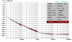
Here’s the phase noise of a commercial Overtone design - Low jitter 100MHz XO module, worrying to such poor results at LF offsets.
Here’s the phase noise of a commercial Overtone design - Low jitter 100MHz XO module, worrying to such poor results at LF offsets.
Attachments
Oem
Hi John,
You are considering ordering 20,000 pieces a year of a crystal and you are asking questions on a Do-It-Yourself-Audio forum????😕
You must be a Original Equipment Manufacturer.
I will help you once and for all with this link.
http://www.sherlab.com/electronics/quartz.htm
For the rest you are on your own, as far as me concerns.
Good luck.
As an audio designer I get to travel all over the world working with OEM’s, and on the other side of the coin, work with semi-conductor manufactures designing the chips that go into these very products.
Of all the companies I work with these days – None and I mean NONE! have anything close to a decent auditioning room & system. Most places I go into, your lucky to even find a pair of matched speakers.
In the semi-conductor industry, nobody seriously listens to there own products, preferring to “listen to measurements” – don’t even try to mention Capacitor sound!
I walk around these companies, and hear comments like “Why bother you can’t hear below –100dB anyway”. I walk past without passing remark – but become more disillusioned, as I know anything I say will “fall on deaf ears” – no pun intended!
So, do I stop working in this industry? No - with the Do-It-Yourself-Audio forum, I’m willing to share my knowledge and designs, and help where I can (and ask for help) – for I know that I’m with others who are truly interested in Audio, and in advancing the art of Audio. I’m with others, whose most important piece of measurement gear – comes down to their very own ears!
Don’t get me wrong, I don’t believe there’s any excuse for a poor measuring system, but that said – the day I hear a Digital system sound as good as a high quality Turntable playing though a Valve OTL amp driving ESL speakers directly, will be the day that I can say Digital has finally delivered on its promise.
So I hope I don’t offend, as a professional in a Do-It-Yourself-Audio forum🙂
20,000 a year!!!
You are joking, right??? Whe the hell is going to buy that many xtals of one frequency in one year??
Any manufacturer large enough to buy that many already has their mind made up, and they aren't going to change it because of you. If they were, they would just get their own engineers to do it and bypass you.
Good luck, bub.......you are really going to need it!
Jocko
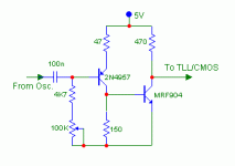
Dunno if it's still relevant, but I just came back upon Matthy's papers I have on EC XO. Here is the buffer he proposes. I haven't checked for the availability of the BJTs used, but we can sure find replacement parts. I haven't tested it, so don't know how it measures in real life...
Just a quote from Matthys about this XO :
"And at 100MHz, the crystal's in circuit Q is 84% of the crystal's internal Q. These are relatively high in-circuit Qs, which should give good short term frequency stability, and they do. The short term stability of these circuits measured 0.1 ppm, at the limit of available measuring equipment. This stability is better than that of any other harmonic circuit tested."
(That was in 1987...)
Just my
Attachments
Re: 20,000 a year!!!
Jocko
They are more flexible in the east and that's why there is strong growth.
Fred
------------------------------------------------------------Jocko Homo said:You are joking, right??? Whe the hell is going to buy that many xtals of one frequency in one year??
Any manufacturer large enough to buy that many already has their mind made up, and they aren't going to change it because of you. If they were, they would just get their own engineers to do it and bypass you.
Good luck, bub.......you are really going to need it!
Jocko
Jocko
They are more flexible in the east and that's why there is strong growth.
Fred
- Status
- Not open for further replies.
- Home
- Source & Line
- Digital Source
- Circuit wanted for a Low Phase noise 100MHz Clock