Jaycar still sells 5W wirewound resistors for 68c. You might get several values for adjustment purposes.

That was based on a 1.5mH inductor, if you need a larger value that will be a bit more of course. The 'guesstimate' uses two caps, two inductors (one large-ish, one small) and two resistors per circuit, so perhaps take the damage as 'best case'.Thanks Geoff, that price doesnt sound to bad.
Geoff
Look into a second order linkwitz Riley and then add an lpad at the end. I can pm you a circuit if you want to see what I mean. For many applications it works well enough and when you say "the woofer could use a little bit more volume" this is a possible fix for that. lpad will bring the tweeter down, the db attenuation is up to you. It's two inductors, two capacitors, and two resistors. The two resistors make up the lpad and they call it an lpad because it looks like the letter L.
Reason not to use lpad: wasted current dumped to ground, but in most applications this can be ignored.
Basically, you have a resistor in series with the tweeter and before that another resistor to ground. Depending on the resistor values and speaker impedance, you'll send some of the juice directly to ground and the rest to the tweeter. Easy and inexpensive way to drop 3 or 5 db on your tweeter and bring it in line with the woofer.
I'm no professional but I have applied this linkwitz Riley crossover circuit four or five times with solid results.
Last edited:
My account is too new, so no can do on that one. I attached a basic crossover file that you can use with VituixCad (its free). It makes poor assumptions regarding the impedance and frequency response of the drivers - which is to say that its assuming a flat impedance unless you obtain or make the appropriate files for each driver. That being said, you can play around with this to get an idea.

The tweeter is a bit hotter than the woofer:

But with the lpad, SPL is nearly the same:

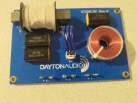
And here is a real life example of that crossover using slightly different component values, M160-8 woofers from the infamous Dannie Ritchie, and GRS PRT-8 phelonic ring 70s tweeters measured on a Dayton umm-6. Sorry for snapping this photo off my projector. Understand that impedance is not linear and selecting the right crossover point and driver pairs is ideal. Check your datasheets when in doubt - and understand that even those are sometimes dubious.

hope this helps. I am open to suggestions from anyone - I do not claim to be an expert, this is just what I have learned.
Note: the resistors ought to be beefy - 10W is safe in most cases as music/movies are dynamic and 10W sustained over the tweeter / parallel resistor is unlikely unless you send it into oscillation. The inductors should be air core if possible, although those are more expensive. Poly film capacitors are the way to go for passive crossover circuits.
The tweeter is a bit hotter than the woofer:
But with the lpad, SPL is nearly the same:
And here is a real life example of that crossover using slightly different component values, M160-8 woofers from the infamous Dannie Ritchie, and GRS PRT-8 phelonic ring 70s tweeters measured on a Dayton umm-6. Sorry for snapping this photo off my projector. Understand that impedance is not linear and selecting the right crossover point and driver pairs is ideal. Check your datasheets when in doubt - and understand that even those are sometimes dubious.
hope this helps. I am open to suggestions from anyone - I do not claim to be an expert, this is just what I have learned.
Note: the resistors ought to be beefy - 10W is safe in most cases as music/movies are dynamic and 10W sustained over the tweeter / parallel resistor is unlikely unless you send it into oscillation. The inductors should be air core if possible, although those are more expensive. Poly film capacitors are the way to go for passive crossover circuits.
Attachments
Last edited:
As an example of how sims differ from actual, here are two FR plots of Paul Carmody's famous "Classix II" speakers: the first is an Xsim model using data supplied by the manufacturers, the second, how it measures in the real world: quite a difference!
Exactly the same crossover parts values were used:


Geoff
Exactly the same crossover parts values were used:
Geoff
Ok to complete the task I need the following from you please:Hi Dave,
Yes this will be of interest. thanks
1. Are you using a single RS180-P and is this the 8 ohm or 4 ohm version?
2. Have you decided on the SB27STAC tweeter?
3. What are your baffle dimensions (height and width)
4. Please provide the driver placement you intend on the baffle (i.e. X and Y edge offset for driver centres). I can place them arbitrarily symmetrically with minimal gap between if you like
5. What box alignment are you going for? e.g. sealed or vented? Either way I'll need the internal volume (Litres or cubic feet) and for vented - your box tuning frequency (Fb)
I would not consider that to be simulator error unless it was done improperly. Simulators are fairly accurate. I'd assume a measurement inconsistency, or.. was this actually a copy speaker measured by a different builder?As an example of how sims differ from actual,
I used Dayton's supplied FR and ZMA files, but fptrace to work out those files for the tweeter from the official Vifa/Tymphany product page; the second graph is from Paul's website so I assume that's accurate.
Other times, the Xsim model isn't too far off the real world but I thought I'd use the Classix as an interesting example
Geoff
Other times, the Xsim model isn't too far off the real world but I thought I'd use the Classix as an interesting example
Geoff
Fair enough. Some things that could vary slightly are the diffraction signature and measured distance, the measurement axis, the microphone response and the vertical positioning which can vary the lobe for phase/summing. This is assuming the measurement is otherwise done properly.
Hi Dave,
Thanks; I will gather all that information. The speakers are already complete and running, and the more i listen, the more i realise that there does need to be a slightly better balance between the tweeter and woofer as I feel the tweeter is more prominent. So if I can succeed in balancing these two, then I will enjoy it more.
Thanks; I will gather all that information. The speakers are already complete and running, and the more i listen, the more i realise that there does need to be a slightly better balance between the tweeter and woofer as I feel the tweeter is more prominent. So if I can succeed in balancing these two, then I will enjoy it more.
Hi Dave,
1. Are you using a single RS180-P and is this the 8 ohm or 4 ohm version? Yes single woofer for and it is 8 ohms
2. Have you decided on the SB27STAC tweeter? Yes already installed its 4ohms
3. What are your baffle dimensions (height and width) How do i measure this?
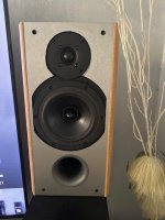
4. Please provide the driver placement you intend on the baffle (i.e. X and Y edge offset for driver centres). I can place them arbitrarily symmetrically with minimal gap between if you like, I have attached ana image that i hope answers that question 🙂
5. What box alignment are you going for? e.g. sealed or vented? Either way I'll need the internal volume (Litres or cubic feet) and for vented - your box tuning frequency (Fb) - This box is vented its about 23-26L in volume.
1. Are you using a single RS180-P and is this the 8 ohm or 4 ohm version? Yes single woofer for and it is 8 ohms
2. Have you decided on the SB27STAC tweeter? Yes already installed its 4ohms
3. What are your baffle dimensions (height and width) How do i measure this?
4. Please provide the driver placement you intend on the baffle (i.e. X and Y edge offset for driver centres). I can place them arbitrarily symmetrically with minimal gap between if you like, I have attached ana image that i hope answers that question 🙂
5. What box alignment are you going for? e.g. sealed or vented? Either way I'll need the internal volume (Litres or cubic feet) and for vented - your box tuning frequency (Fb) - This box is vented its about 23-26L in volume.
Attachments
I'm assuming there is no acoustic offset and no Y offset either (i.e. both manufacturer measurements are on driver axis,not listening axis). These 2 combined will have as you know phase relationship misalignment at the crossover and the woofer tailing off sooner in the real world, meaning the designers attempt to LP the woofer may be too aggressive with an rolloff already occuring due to Y axis offsetFair enough. Some things that could vary slightly are the diffraction signature and measured distance, the measurement axis, the microphone response and the vertical positioning which can vary the lobe for phase/summing. This is assuming the measurement is otherwise done properly.
Re baffle and driver placement. please measure each colour and tell me the units - CM or inches or parsecs etc... 😀
For the purple / brown - these are the distances from the top of the baffle down to the centre of the tweeter dome and centre of the woofer (Y axis). there is no need to measure the horizontal for where the drivers are on the baffle as you have made them midway (i.e. for me = RED / 2)

For the purple / brown - these are the distances from the top of the baffle down to the centre of the tweeter dome and centre of the woofer (Y axis). there is no need to measure the horizontal for where the drivers are on the baffle as you have made them midway (i.e. for me = RED / 2)
For box alignment - can you please tell me the inner diameter of the port and overall port length (from outside edge of flares on each end)
Thanks Dave, blue is 7 cm, purple brown is 21.5cm, Green 45cm. Port 20cm in diameter and port length is 14cm.
If you are interested, I could model a crossover with your Dayton off the shelf version when I've done all the FRD/ZMA files. I can read the capacitor values in the photo, but are the inductor "mH" values printed anywhere?
- Home
- Loudspeakers
- Multi-Way
- choosing tweeter for DIY