I've been playing around with paralleling a pair of low power SE amps lately.
I know that a series resistor is required to deal with imbalances, but is there any logic to the choice of value for the series resistor?
There are plenty of examples in the opamp world for paralleling amps, but I've only seen stated values. For example, an article which uses the LT6020 says:
So is there any formula, logic or 'best practice' reason to choose a particular value over another?
I'd also like to ask about the correct way to connect a pair of single ended amps:
Most of the schematics / guides are based around opamps, and therefore mainly figure the 'triangle' symbol in their example for connection. Somewhat stupidly, I've thought that I can just simply apply that to an AC coupled amp. So I paralleled before the output capacitor (to save capacitors...). But now I've read that you can't have a DC offset where the amp is paralleled (damn you, zero DC offset output op-amps!) and that particular node sits at 2/3VCC. Oops. 😱
So I guess the second question is: paralleling before the output cap on an AC coupled solid state amp is definitely not a good thing? It has to be after the coupling capacitor?
I know that a series resistor is required to deal with imbalances, but is there any logic to the choice of value for the series resistor?
There are plenty of examples in the opamp world for paralleling amps, but I've only seen stated values. For example, an article which uses the LT6020 says:
But no rationale is given as to why choose that value. Other sources talk about using anything from 10 ohm down to 0.33 ohm.The 100Ω resistors at the output prevent the paralleled amplifier outputs from fighting with each other.
So is there any formula, logic or 'best practice' reason to choose a particular value over another?
I'd also like to ask about the correct way to connect a pair of single ended amps:
Most of the schematics / guides are based around opamps, and therefore mainly figure the 'triangle' symbol in their example for connection. Somewhat stupidly, I've thought that I can just simply apply that to an AC coupled amp. So I paralleled before the output capacitor (to save capacitors...). But now I've read that you can't have a DC offset where the amp is paralleled (damn you, zero DC offset output op-amps!) and that particular node sits at 2/3VCC. Oops. 😱
So I guess the second question is: paralleling before the output cap on an AC coupled solid state amp is definitely not a good thing? It has to be after the coupling capacitor?
It is not worth paralleling amp with resistor.
Any resistor you added will increase output impedance of the amp. With reactive load like a speaker, you get none flat frequency response.
The thing you can do is to bi-amp your speaker. Check if you have electrically separated 2 sets of binding posts on your speaker.
Any resistor you added will increase output impedance of the amp. With reactive load like a speaker, you get none flat frequency response.
The thing you can do is to bi-amp your speaker. Check if you have electrically separated 2 sets of binding posts on your speaker.
The closer matched the two amps are in terms of their voltage output and the lower the value of resistor you can use.
Much does depend on the amps themselves. Think about it 🙂 and think of the amps as two fixed voltage sources. Say one amp puts out 10 volts and the other puts out 10.1 volts.
If the amp has a very low output impedance of a fraction of an ohm (typical solid state amp) then that difference means a large current will flow between the amps. Not good.
If the amp has a high output impedance (like the ACA) then that impedance swamps any such effect and little circulating current flows.
DC offset is important. If not identical then large currents will flow. If the amp is an AC coupled one then any difference in midpoint voltage will do the same. So yes, paralleling after an output coupling cap is important.
Don't overthink it trying to understand it. Think of two batteries, if both have the same voltage you can parallel them. Any difference and current will flow. How much current depends on the internal resistance of the battery.
Opamps work well for paralleling because the DC conditions and gain are so precisely defined. Two identical discrete amps will differ far more.
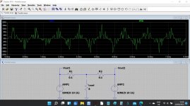
Look at this simulation.
Two identical amplifiers (NO load attached) and we are looking at the current flowing between them. The output is a 10v peak sine. NO circulating current flows because both are identical.
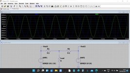
Second image has 0.1 volt difference in output between the two amps. Now look at the circulating current as the amps 'fight' each other.
Look at the scale in the first image. Femto amps. There is no measurable current flow because both are perfectly matched.
Two identical amplifiers (NO load attached) and we are looking at the current flowing between them. The output is a 10v peak sine. NO circulating current flows because both are identical.
Second image has 0.1 volt difference in output between the two amps. Now look at the circulating current as the amps 'fight' each other.
Look at the scale in the first image. Femto amps. There is no measurable current flow because both are perfectly matched.
Attachments
First tabulate all possible sources of mismatch between amplifiers and quantify them. With opamps the first two items in the list are usually (i) unequal input offset voltage; (ii) unequal closed loop gain due to feedback network tolerances.
Now calculate how much current flows out of the output of amplifier_1, through both external resistors, into the output of amplifier_2. Give it a memorable and colorful name, perhaps FIGHT-CURRENT. Naturally the fight-current varies as you change the external resistor value.
Now use your design intuition and your years of experience and your gutt feeeling and your gambler's instincts, to decide how much fight-current you can accept. 15% of Iout_max? 1%? You choose. Then select a value of external resistors that guarantees the fight-current will be less than or equal to your self imposed limit.
Done.
If you own Douglas Self's Small Signal Audio book, look up "Mothers Little Helper". He likes it; do you?
Thanks for the answers!
I don't really want to get into why or why not parallel an amp; just suffice to say that there are reasons that I am playing with parallel configurations.
Thanks for the simulations Mooly. I could always use the .step param command there to graph a best choice for a given error voltage.
Mark, in terms of how much 'fight-current' a particular transistor will endure, if the amplifier only utilises up to 50% of Iout_Max (for example), would that affect the fight-current limit choice?
And I wish I could find the SSA book for under $100aud.
PLEASE post relevant schematics.low power SE amps
2) please define
just suffice to say that there are reasons that I am playing with parallel configurations.
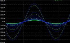
This is what the sim shows for a selection of resistors from 1-10 ohm using a 10v signal with 10% error:
So 10 ohms seems to be quite effective.
Remember that an unknown is the output impedance of the actual amplifiers themselves. The sims are' perfect' voltage sources unless you add a little resistance.
Attachments
- Home
- Amplifiers
- Solid State
- Choosing a parallel amp resistor