We have to keep in mind that for inductances above the critical one, the current through the L will not decay to zero, but the rectifiers in the bridge will still switch off for half a period. Although that is already a lot better than with a normal bridge + cap approach where you could speak about Class C behaviour of the rectifiers (conducting only in narrow peak, far less than 180*), if you would like to make an analogy with amplifier classes. With L above the critical inductance, the rectifiers would be in Class B then (conducting 180*). I haven't simulated it, but I think snubbers could still be useful.
For the difference between LC filters and CLC filters, I would like to draw your attention to http://www.qsl.net/i0jx/supply.html
Steven
For the difference between LC filters and CLC filters, I would like to draw your attention to http://www.qsl.net/i0jx/supply.html
Steven
Steven said:I haven't simulated it, but I think snubbers could still be useful.
If the diodes switch I think a good snubber cct is essential otherwise the coil will ring like crazy when the diode turns off.
a snubber cct here is more important than with a normal transformer PSU because there, you at least have the primary coil effectively damping the potential oscillations in the secondary.
In this cct, if the diodes switch, the inductors just sing away with complete abandon - could completely trash the sound
john curl said:Mike, you are getting me worried! ;-) I design power supplies like this. Ask Sy, I showed him one, last week.
Thanks John,
this is encouraging. I feel good about this design.
would you think a high quality mu metal inductor would be best here or would a rewound and air gapped microwave tranny be OK ?
I don't want to waste money but I also don't feel like compromising on this one.
Free Inductors..........
Mike,
Graham (Circlotron) has experimented with microwave ovens as a cheap source of high power transformers/inductors with air gap built in.
If you search 'microwave' you may find the thread.
Eric.
Mike,
Graham (Circlotron) has experimented with microwave ovens as a cheap source of high power transformers/inductors with air gap built in.
If you search 'microwave' you may find the thread.
Eric.
If the diodes switch I think a good snubber cct is essential otherwise the coil will ring like crazy when the diode turns off.
The diodes turn off and on but the choke does not
see this and the current in it is very good.
Federico
Steven said:In fact, if the value of the choke is above the critical value (approx L=Vdc/1000Idc for 60Hz with double phase rectification and 20% more for 50Hz mains, e.g. 30mH for 50Vdc, 2Adc and 50Hz mains) the current through the rectifiers will never switch off.
Steven
that doesn't seem to be consistent with my simulation (using ltspice).
care to explain why?
Hi
It is not a Class A no switching PSU.
The diodes alternatively switch off. Yes, there are no current spikes in the diodes but the current drawn from the transformer is a 60 Hz square wave plus a 120 Hz sinus.
Not so good.
I we need a better current shape in the trafo
we have to add chokes also between trafo e diode bridge.
Obviously, the DC voltage at the load will decrease.
Regard
Federico
fscarpa58 said:Hi
It is not a Class A no switching PSU.
The diodes alternatively switch off. Yes, there are no current spikes in the diodes but the current drawn from the transformer is a 60 Hz square wave plus a 120 Hz sinus.
Not so good.
I we need a better current shape in the trafo
we have to add chokes also between trafo e diode bridge.
Obviously, the DC voltage at the load will decrease.
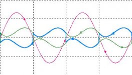
well spotted, I also just simulated and found what the tranformer Voltage and current is doing - but is it really 'Not so good' ?
below is a plot of the V & A in the tranny
I understood that a transformer is most easily able to deliver current when the rate of change is greatest so having a having a steep rise in current here is not a bad thing and the current rise time for that part of the cycle I noticed is about 87uS, not that fast.
So the diodes are switching, but significantly, I think, the current never comes to a full stop so the whole process seems to me to be significantly less violent than the normal setup.
I think I will leave snubber type caps on both sides of the diodes, build it and see how it sounds
cheers
mike
Attachments
mikelm said:So the diodes are switching, but significantly, I think, the current never comes to a full stop
mike
mike, how can the diodes are switching yet the current doesn't come to a full stop? if a diode is switching, it much have come to reverse biasing during portions of its cycles. right? then the current going through the diode must have come to a full stop (when reverse biased).
going back to the l/c type filtration. It is certainly superior to the r/c type filtration which is really a more advanced form of the traditional c type filtration (filter only).
I just don't know, however, if such elaborate set-up justifies its associated costs, especially when used with an amp with high psrr.
in all the amps I have built, humming has been a problem. Knock on wood, 🙂
I think I get the point. Reading about Flyback smps, about continious and discontinious mode helps me.
If the L is big enough (Steven's value=30mH) and the output current is continious, the diodes are still switching, but the inductor somehow "deposit" current, so the output current from this inductor is always there (class A?).
This can be achieved if the L is big enough (Mikelm, have you tried 30mH instead of 2 or 1mH in your simulator?) and the current draw by the audio power amp is continious big value (class A / single ended). With class B audio power amp, this will not merits so much as is in class A audio power amp.
If the inductor is small value, or current draw is small, this same LC configuration will only do ripple filtering.
... so the whole process seems to me to be significantly less violent than the normal setup.
Mike,
I completely agree with you. Inductive PSU are, by far, better than capacitative ones, and this is well known.
However it is worth to note that current drawn from the trafo is still characterized by the presence of high order terms which can produce electro-magnetic effects (RF) on the other component of the audio system both through the air and the cables.
If the target is the electric net ( I have not a better word) see the amp as a resistive load (sinusoidal current shape) than some filtering before the diode bridge is required.
Bye
Federico
millwood said:mike, how can the diodes are switching yet the current doesn't come to a full stop? if a diode is switching, it much have come to reverse biasing during portions of its cycles. right? then the current going through the diode must have come to a full stop (when reverse biased).
I just don't know, however, if such elaborate set-up justifies its associated costs, especially when used with an amp with high psrr.
in all the amps I have built, humming has (not ?) been a problem. Knock on wood, 🙂
sorry I should have said current in the transformer coils does not come to a full stop - I discovered yesterday that the diodes do switch.
The fact that their are not full stops I think will help the sound.
When, in a normal supply, the diodes switch, instantly, the secondary coil has to stop delivering current. The secondary coil, having some inductance, will not like this and would, if left to is own devices, oscillate at high frequency. The only reason, I believe, that I have never seen this on a scope is because what is happening in the sec & pri of a tranny are quite closely magnetically linked and the P effectively damps any tendency for ringing in the S, conversly though, the S will tranfer some of the switch off transient shock back to the P - with voltage amplified on average about 10 times ( in the UK ) - and pollute the mains supply with it.
Can you imagine right now how many PS's are switching like this in your town, city, country etc. no wonder the mains needs conditioning for best reproduction. And no wonder also that many reports of hi-fi shows speak of the much of the equipment sounding very dissapointing. The more big amps that are plugged in the bigger the mess becomes. ( unless they are designed by JC ;-) )
I said that I had never seen this on a scope but I have heard the huge difference that filtering all this stuff out of a supply can make.
The simplest, biggest thing to try is to put a 4.7uF film cap directly across the S coil. This will, in conjuction with the damping of the P, drastically reduce the frequency, amplitude and duration of the effect descibed above and really improves the sound.
I have not used choke regulation to try and eliminate hum but rather filter out some of the hum and eliminate as much as possible the RF & HF junk that comes along with it from both my own PSU and everyone else's. PSRR is most often not very effective at the kind of high frequencies we are talking about here.
I have found that choke regulation allows amps to sound beautifully smooth and natural ( if it's a good amp ! )
I hope this makes sense to one or two people out there !
regards
mike
lumanauw said:I think I get the point. Reading about Flyback smps, about continious and discontinious mode helps me.
If the L is big enough (Steven's value=30mH) and the output current is continious, the diodes are still switching, but the inductor somehow "deposit" current, so the output current from this inductor is always there (class A?).
This can be achieved if the L is big enough (Mikelm, have you tried 30mH instead of 2 or 1mH in your simulator?) and the current draw by the audio power amp is continious big value (class A / single ended). With class B audio power amp, this will not merits so much as is in class A audio power amp.
If the inductor is small value, or current draw is small, this same LC configuration will only do ripple filtering.
My cct has standing current of 6 amps. In these circumstances the choke values that I have used are just OK to stop the current switching off ( I'll reply to you other mail soon )
regards
mike
After reading the article that Steven pointed, it seems that this advantage can be achieved by LC configuration. In CLC, the first C already makes DC, so the rest LC is only lowpass. Is this right?
One other thing. In this same article, there is a C parrarel to L, to get ringing choke. Is this needed if we talk about audio PS?
One other thing. In this same article, there is a C parrarel to L, to get ringing choke. Is this needed if we talk about audio PS?
if the first C of the CLC is small enough the circuit behaves
like an LC net (approximately).
Federico
like an LC net (approximately).
Federico
After reading the article that Steven pointed, it seems that this advantage can be achieved by LC configuration. In CLC, the first C already makes DC, so the rest LC is only lowpass. Is this right?
One other thing. In this same article, there is a C parrarel to L, to get ringing choke. Is this needed if we talk about audio PS?
lumanauw
Yes the rest is a low pass filter - my chief aim is HF & RF filtration.
A ringing choke would reduce HF & RF filtration so I don't plan to to do this
if the first C of the CLC is small enough the circuit behaves
like an LC net (approximately).Federico
Frederico
Not quite sure what you mean when you say 'small enough'. In class A power amp applications in which I think this PSU would excell there would be a problem getting lets say a 1000uF cap with a high enough ripple current capability.
There is nothing smaller than nothing - could we settle for this ?
what did you have in mind ?
with no cap we do have a LC net don't we ?
I'm not quite sure what point you are making here.
there would be a problem getting lets say a 1000uF cap with a high enough ripple current capability.
This reminds me that once I have encounter that in CLC configuration, the very first C (after bridging diode) is headed with very vigorous operation condition. This first C usually don't live as long as the C after the L (if we use the same C for both).
Maybe what Federico saying is the first C is about 100nF, while the second C is 100.000uF? But not having any of the first C is the best, I think, to get this merit of Continious Current from the Choke.
mikelm said:
My cct has standing current of 6 amps. In these circumstances the choke values that I have used are just OK to stop the current switching off ( I'll reply to you other mail soon )
regards
mike
Mike,
I think it would be a good idea to connect a resistor in parallel to your choke(s) as a kind of snubber. Value guideline: about 10...100 Ohm. Then you can use much smaller snubber capacitors across the bridge.
Steven
Steven said:Mike,
I think it would be a good idea to connect a resistor in parallel to your choke(s) as a kind of snubber. Value guideline: about 10...100 Ohm. Then you can use much smaller snubber capacitors across the bridge.
Steven
OK I'll try resistors and see how it looks.
I am aware that the snubber cct can use much lower values even without these resistors but I prefer the larger values because as well as reducing the amplitude and time of ringing, larger caps substantially reduce the frequency ( to a few KHz.) Seems like a good idea to me.
I'm interested if you or others have ever tried 4.7uF directly across the secondary in a normal supply.
No one ever seems to comment when I mention this idea which I find strange becauce this is the best, easiest tweek I have ever discovered. no matter what cct I have tried it on, it has always made a big improvement.
mike
- Status
- Not open for further replies.
- Home
- Amplifiers
- Solid State
- Choke for Pi Filter