Still not working, pin 2 and 3 were also reversed.
Changed this in schematic and ordered new PCB's.

Changed this in schematic and ordered new PCB's.
Assuming Q3 is the SOT-223 package, it appears to me that the pin-out of Q3 (LM317) on your schematic is not correct.

Who got this amp (10W Lineup's design) up and playing?
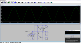
My build is based on Zoltan's stereo PCB (thank you Zoltan).
What is recommended heatsink size/model?
For my first test I have used 150mm x 150mm x 3mm steel panel (5" x 5" x 1/8") and IMO it's too hot after 5 minutes.
PS at main capacitors is +/- 16V.
BTW, I like the sound.
My build is based on Zoltan's stereo PCB (thank you Zoltan).
What is recommended heatsink size/model?
For my first test I have used 150mm x 150mm x 3mm steel panel (5" x 5" x 1/8") and IMO it's too hot after 5 minutes.
PS at main capacitors is +/- 16V.
BTW, I like the sound.

Benpe
I'm glad everything is OK and that you didn't have any problems with starting
I mentioned that we need a large heat sink
We have about 400mA of quiescent current
With a power supply of about +/- 16V for two channels we have 26W of heat to dissipate.....
Mine is 170 x 40 x 80mm It's warm but not hot
I'm glad everything is OK and that you didn't have any problems with starting
I mentioned that we need a large heat sink
We have about 400mA of quiescent current
With a power supply of about +/- 16V for two channels we have 26W of heat to dissipate.....
Mine is 170 x 40 x 80mm It's warm but not hot
important info
there is no ground connection on the PCB at the input of one of the channels
I connected the grounds on the input sockets and did not notice any problem!
afternoon I improved the gerbers
people who received the PCB from me - please connect the grounds on the input sockets!
Sorry !!!!
there is no ground connection on the PCB at the input of one of the channels
I connected the grounds on the input sockets and did not notice any problem!
afternoon I improved the gerbers
people who received the PCB from me - please connect the grounds on the input sockets!
Sorry !!!!
Might even be a feature, not a bug - to avoid ground loops...Sorry !!!!
Final version, this weekend gone bridge two of them.
Pin 1 and 3 of LM317 was reversed in schematic.
Changed R5 and R8 from 4k7 to 7k5.
New schematic and measurements will follow.


Pin 1 and 3 of LM317 was reversed in schematic.
Changed R5 and R8 from 4k7 to 7k5.
New schematic and measurements will follow.
could i use something basic like the irf540/9540?It is okay with SK1058/J162
at these levels of thd just choose the cheapest rail to rail you can findI tested OPA1655.
It is almost as good as OPA2156 and also better than OPA1641.
THD 0.00006%
So, now I recommend OPA1655, a single channel opamp.
what if i were to run the bias and op amp circuits at a higher voltage?
here is my "spin" on the amplifier i did forget a few parts but the most important thing is running it in relatively high bias class AB the 7.48KΩ resistor is an 680 ohm and an 6.8kΩ represented as a single resistor, if such a thing as an dual trimmer potentiometer actually exists id be happy use it here as an replacement for the resistors so you can adjust the bias more precisely.Here is the new Choctaw circuit. It is the 19th version I have in my computer!
New is the compensation cap 22pF to the opamp out.
I added also a cap across the feedback resistor 47pF.
This 47pF is to see as a lowpass filter. Reduces -3dB bandwidth to 200kHz.
Distortion simulated is THD 0.00093%
PhaseMargin is 76 Deg.
I hope this will be the Final circuit.
Oh, missing are the decoupling caps around the opamps supply rails. Two 100nF caps
Attachments
One NPN transistor on heat sink, one resistor and one pot will do thermal compensation for those vertical fets, much cheaper than burning up amp and speaker 🙂... Somewhere in this thread is photo of my amp with IRF's that works for last 30 yearsprobably not. but hey im broke and dont have the money for latfets
do they work with mosfets? and how to calculate one for mosfets. also i would have to put the op amp somwhere else.Add Vbe multiplier
In its current form the amplifier will burn out
As shown, I agree with the previous posts; it will likely self-destruct. Adding a vibe multiplier and transistor on the heatsink will help stabilize the circuit, but you may need to consider how the asymmetrical feed of the opamp to the output transistors will affect the output voltage swing. Vertical mosfets usually have a higher threshold voltage than laterals, which may also affect things. Another concern is the high impedance path from the opamp output to the transistor gates.
Good luck with it.
Good luck with it.
- Home
- Amplifiers
- Solid State
- Choctaw - 10 Watt Amplifier, 1 Opamp + 2 MOSFET