Lol, that rev C is a way underutilisation of that carver case.
Absolutely but the price was good (free)... 😀
PS, so I passed that cost on to the owner.
2xtda7294 & IR2153

sorry for repeat, images are lost...

An externally hosted image should be here but it was not working when we last tested it.
sorry for repeat, images are lost...
My 4 channel LM3886 amp
Hello everybody,
I have been looking around this tread for some time now, so I thought let's post some pictures!
The amp is based on the BrianGT PCB, the power supply consists of 2 SMPS (26V 13.2A) working as a bipolar supply with a lot of added filtering. For this filter I made my own inductors which work perfectly well for this application! The amp is used to actively bi-amp my monitor speakers (I use an active Samson Audio XO, 3 way 24dB LR). The monitors are now being build (no XO in the monitor except for a capacitor to protect the tweeter from any DC).
The input connectors are BNC connectors, just because I could reuse them from an old device which I scrapped at work.
The performance so far is very good, just need to do something about the fans of the SMPS which can be a bit loud after some time.


Hope you all like it!
Hello everybody,
I have been looking around this tread for some time now, so I thought let's post some pictures!
The amp is based on the BrianGT PCB, the power supply consists of 2 SMPS (26V 13.2A) working as a bipolar supply with a lot of added filtering. For this filter I made my own inductors which work perfectly well for this application! The amp is used to actively bi-amp my monitor speakers (I use an active Samson Audio XO, 3 way 24dB LR). The monitors are now being build (no XO in the monitor except for a capacitor to protect the tweeter from any DC).
The input connectors are BNC connectors, just because I could reuse them from an old device which I scrapped at work.
The performance so far is very good, just need to do something about the fans of the SMPS which can be a bit loud after some time.
Hope you all like it!
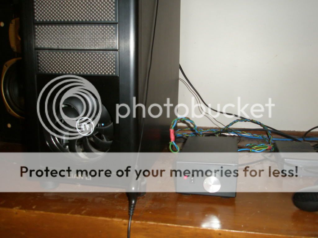
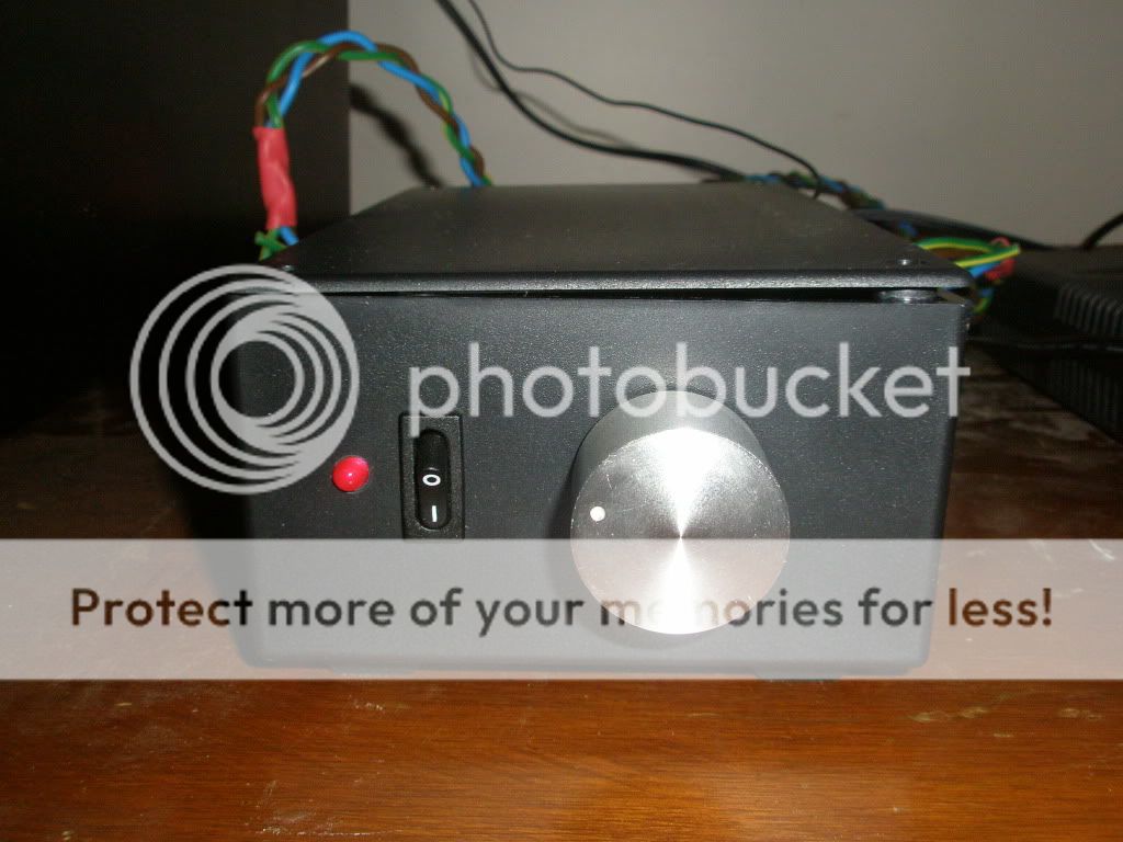
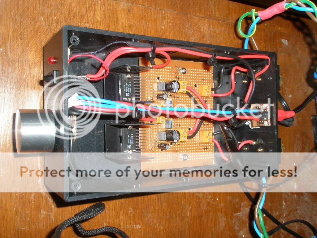
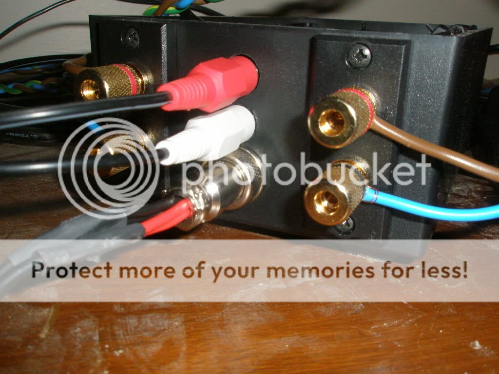
TDA1519A based amp
Here is a little 22watt x2 12v chipamp I built for my computer based off the TDA1519A amp, each chip is stereo at 11 watts but by bridging the two inputs and one capacitor at pin 3 you can change it to Bridge mode, quite a nice sound at 22watts powering Tannoy Eclipse speakers from the 70's
Note there is an external 5 amp 12v Switch Mode PSU which is also to a surprise pretty good.
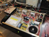
Attached is a photo of my almost completed chip amp. Some notes:
- LM3886 based Chip Amp from DIY Chip Amplifier Kits, PCB's, Components and Information..
- 22+22V 220 VA toroid transformer
- Two other power sources - 5 V for the controller and wireless remote control, and 12-12v for preamp, cd, etc.
- XBee for the wireless remote control (top left)
- AR1000 FM receiver (tiny almost invisible chip in the top left under XBEE)
- Preamp board, using MC14052 for input selection, and PGA 2310 for volume control.
- Computer CDROM, with external SPDIF / DAC. The audio out of the CDROM wasn't so good - well, pretty bad actually.
- PIC 18F4423 as the system control. Most of the pins are required for the ATAPI interface to the CDROM. Coding up the ATA/ATAPI interface was no trivial task. It took months.
On the far left, is the remote control. I carved this out of a piece of wood. Made the buttons. It uses a PIC 16F688, an XBee transmitter. Runs on 2 x AAA batteries.
I didn't intend this to be the best performance system, but it does pretty good.
Richard
Attachments

good job, richard! xbees are cool, aren't they? (I just started my own xbee based project, in fact).
Thanks. It's taken 2½ years, although I had to take 1½ years off in the middle for other things.
I'd originally developed an IR interface using the Phillips RC5 protocol. However, open electronics shelves don't go with our home decor, and IR repeaters don't work so well. So I switched over to XBee. It's a lot easier to use - it takes care of the communications protocol for you. Much more expensive though.
I'd originally developed an IR interface using the Phillips RC5 protocol. However, open electronics shelves don't go with our home decor, and IR repeaters don't work so well. So I switched over to XBee. It's a lot easier to use - it takes care of the communications protocol for you. Much more expensive though.
having both an IR and an RF solution is always nice. my project was all IR until about a week ago. the xbees split the device into client/server and you split your code that way, too, right when it 'writes' to the volume control engine or i/o selector engine. $30 each radio side, though, and that's kind of expensive.
Re client / server. I'm embarrassed to say that I don't remember. Probably. I'll have to go look at the code this evening.
I must say that the PIC firmware was by far the most difficult part of the project.
I still have a couple of FW defects to fix, then I'm good to go!
Richard
I must say that the PIC firmware was by far the most difficult part of the project.
I still have a couple of FW defects to fix, then I'm good to go!
Richard
don't feel bad; I also spent (over) a year and a half puttering around with the firmware. I consider my project to be *mostly* a software development and to a much lesser extent, hardware. the hw was done for months and months, but the sw bugs needed to be down to zero or near-zero before release. the last few sometimes cause a redesign of the sw and things end up taking forever.
...know the feeling extremely well 😉
...know the feeling extremely well 😉
hey richard, can you give us some more close-ups of the remote, outside and inside? I'm going to be making a remote of my own, eventually, and would love to see how you approached and solved it.
My biggest problem was trying to engineer a solution to the mess otherwise known as the ATA/ATAPI CDROM interface spec. Then, there was attempting to understand the worst programming manual known to mankind - otherwise known as the AR1000 FM Receiver programming manual. (Well, perhaps the ATAPI spec was worse). I actually obtained an AM/FM receiver module from another company, and I couldn’t even figure out how to interface to that. A knowledge of Mandarin would have helped.
I'll take some more photos of the remote this evening.
Richard
I'll take some more photos of the remote this evening.
Richard
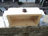
Two images of the remote attached. I built as follows:
i. Basically carved the case out of a block of wood.
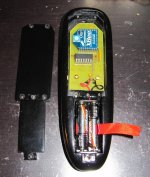
ii. There are two spaces in back - one for the electronics, and one for the battery.
iii. I drilled holes through to the front, and used two different width lengths of dowel - Probably ¼ and ⅜ inch. I glued a wider piece of plastic on the bottoms, so that they wouldn't come out through the front.
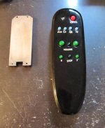
iv. The PCB has surface mount pads on the back - and I soldered surface mount switches. These line up with the holes and dowels.
v. Lots of sanding, paint, lacquer, etc to get a shiny finish. Got paint from the local hobby shop.
vi. Used Dri-transfer lettering for the letters.
i. Basically carved the case out of a block of wood.
ii. There are two spaces in back - one for the electronics, and one for the battery.
iii. I drilled holes through to the front, and used two different width lengths of dowel - Probably ¼ and ⅜ inch. I glued a wider piece of plastic on the bottoms, so that they wouldn't come out through the front.
iv. The PCB has surface mount pads on the back - and I soldered surface mount switches. These line up with the holes and dowels.
v. Lots of sanding, paint, lacquer, etc to get a shiny finish. Got paint from the local hobby shop.
vi. Used Dri-transfer lettering for the letters.
Attachments
CRST that is most resourcefull. I see Xbee module as a basis and combined with hand made wood remote. Well I just got to hand it to you.
If you don't need too many buttons, the ebay RF remotes can be
a quick-n-dirty (and cheap) solution. The buttons can be set to
multiple modes (latch, momentary-on etc) via jumpers. Like these -
4 CH 315M RF Wireless Remote Control Controller 4 Relay | eBay
8 Ch RF remote
a quick-n-dirty (and cheap) solution. The buttons can be set to
multiple modes (latch, momentary-on etc) via jumpers. Like these -
4 CH 315M RF Wireless Remote Control Controller 4 Relay | eBay
8 Ch RF remote
Last edited:
the cool thing about the xbee is that its bi-directional. crst is only using it for one direction (send only) and so the simple rf remotes probably would have been sufficient (and cheaper).
however, if you need to get info FROM your system (for some reason) then you need the xbees. my system will query the base for some info, then update itself locally from that info. for me, I need both directions.
however, if you need to get info FROM your system (for some reason) then you need the xbees. my system will query the base for some info, then update itself locally from that info. for me, I need both directions.
Funny you should mention that. I was just planning my next project with just something like that in mind. I have an older, higher quality project, that I would like to rework.
You'll notice that in this project, there are no controls on the front panel at all. Everything is controlled through the remote. Given an FM tuner, CD player, two aux inputs, volume etc, that's a lot of stuff, and I'm quite pleased that I got it all down to just 12 buttons - that my wife can understand.
I was thinking that for my next system / remote, I'd add the ability to display (volume, CD tracks, station, etc) on the remote itself. You can get relatively inexpensive TFT panels now. Carve a nice case, a little firmware, rechargeable batteries, and perhaps I have something.
Opps.. Sorry, getting carried away.
Richard.
- Home
- Amplifiers
- Chip Amps
- Chip Amp Photo Gallery