...
I wrote a quick and dirty guide below for bending aluminium if anyones interested in making their own chassis
http://bit.ly/d7ayVE
 Cheers mate - very helpful indeed!
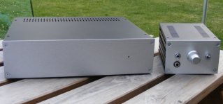
A few pages back i showed the start of my bpa 300 for my subwoofer. The amplifier will have a dual purpose. It will be swticheable beteen bridge and stereo more.
The filter circuit containing a linkwitz transform and parametric EQ can be switcheable. this circuit also contains the inverting and non inverting output for bridge mode.
In the last photo you can see it sitting next to my other gainclones.
The filter circuit containing a linkwitz transform and parametric EQ can be switcheable. this circuit also contains the inverting and non inverting output for bridge mode.
In the last photo you can see it sitting next to my other gainclones.
An externally hosted image should be here but it was not working when we last tested it.
An externally hosted image should be here but it was not working when we last tested it.
An externally hosted image should be here but it was not working when we last tested it.
An externally hosted image should be here but it was not working when we last tested it.
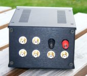
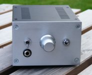
My finished LM3875 dual mono Audiosector premium kit. Passive attenuator is an Alps Blue (50k dual log, with a 47k metal film shunt). Dual input, dual output. It also contains a Sekerez designed class A, single MOSFET (per channel) headphone amp, which is completely switched out of the Gainclone circuit.
Chris.
Chris.
Attachments

Looks great!
A newbie question. What is the purpose of the 47K shunt resistor before the pot?
A newbie question. What is the purpose of the 47K shunt resistor before the pot?
Looks great!
A newbie question. What is the purpose of the 47K shunt resistor before the pot?
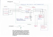
You'll notice that the pot is connected to the ground connection. The 47k resistor and the 50k pot make up a simple voltage divider network. The output (to the power amp) is taken from the centre of the voltage divider network. This means that none of the signal goes through the wiper of the pot. The pot is effectively out of the system, which in my opinion yields sonic improvements.
Chris.
dude, I am so trying that
You'll notice that the pot is connected to the ground connection. The 47k resistor and the 50k pot make up a simple voltage divider network. The output (to the power amp) is taken from the centre of the voltage divider network. This means that none of the signal goes through the wiper of the pot. The pot is effectively out of the system, which in my opinion yields sonic improvements.
Chris.
Very nice amp there. I have a question about your heat sinks. Do they get hot? I think they are too small. I would put one big one.
Very nice amp there. I have a question about your heat sinks. Do they get hot? I think they are too small. I would put one big one.
LOL.. Funny.
Very nice amp there. I have a question about your heat sinks. Do they get hot? I think they are too small. I would put one big one.
The chips are mounted to the back pannel, which takes away most of the heat through the chassis. The small heat sinks are there to asist when the volume gets loud😉.
my amp
non-inverting lm3875
non-inverting lm3875
An externally hosted image should be here but it was not working when we last tested it.
An externally hosted image should be here but it was not working when we last tested it.
My LM4875 build
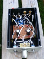
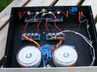
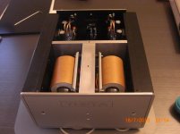
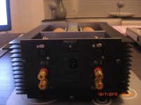
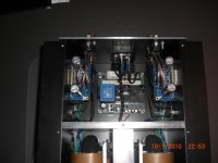
My build. One is finished, another one to go. I am waiting for a power switch for the front and then it is completely finished. It is a dual mono amp and i need two o these for my active stup.
The R-core transfomers are 200VA a piece. The amps com from Peter Daniel. Each channel uses a bridged LM4875 for my balanced setup.
Before i start on the second identical chipamp, i will first finish the prototype of my pre amp with integrated passive crossover. It features
- Balanced circuit
- 6 balanced B1 buffers (+3 if a subwoofer crossover is added)
- Modular PLLXO passive crossovers, between the B1 buffers
- battery power supply
- a 46 step attenuator
- transformers for unbalanced to balanced conversion
You can see more on this thread: http://www.diyaudio.com/forums/pass-labs/153447-two-b1-crossover-new-post.html
Attachments
The chips are mounted to the back pannel, which takes away most of the heat through the chassis. The small heat sinks are there to asist when the volume gets loud😉.
it looks nice. long time ago I build some of these guys too I know they do not get hot (unless you push them to the max). Good job!
- Home
- Amplifiers
- Chip Amps
- Chip Amp Photo Gallery