why do you want to parallel a pair of 8ohm drivers to give a 4ohm load and then give yourself the difficulty of designing a current limited chipamp that can adequately drive that low impedance load?
Use two amplifiers, each designed to drive an 8ohm load and dedicate one amp to one driver.
Fit each driver to it's own separate volume inside your box (sealed or vented) and if one driver or amp goes faulty you can still reproduce live music, just not as loud.
Use two amplifiers, each designed to drive an 8ohm load and dedicate one amp to one driver.
Fit each driver to it's own separate volume inside your box (sealed or vented) and if one driver or amp goes faulty you can still reproduce live music, just not as loud.
Thanks AndrewT for helping me how to plan this amp. You have a good idea 🙂, in the case of two bridged amp, i think i'll have to move to LM3886 chipamp. Thanks a lot guys.
my first LM3886
Hi to everybody...
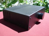
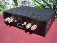
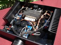
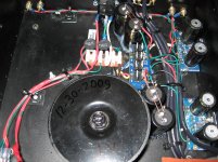
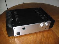
Here is my first LM3886 Chip Amp using PCBs Kit from: eBay Store - HiLife-store: DIY-Audio
Most part are recycled except for the input/output connectors,
The chassis was built in the steel plate of the 360 x 280 mm
The cover is from an old Video Cassette VHS Player
The power switch and AC Socket is from a died PC AXT power supply
The split/dual pot volume control & knob was the a cassette deck.
The power supply is a transformator 2x20V 5A.
The front plate is made a piece 5mm thick of aluminium and black anodize finish
I really had fun with the amp. The sound is clean and fast
Thank you to the diyAudio community for providing me information to build this project,
Happy new year everyone
Sorry, my english is not so good
Hi to everybody...
Here is my first LM3886 Chip Amp using PCBs Kit from: eBay Store - HiLife-store: DIY-Audio
Most part are recycled except for the input/output connectors,
The chassis was built in the steel plate of the 360 x 280 mm
The cover is from an old Video Cassette VHS Player
The power switch and AC Socket is from a died PC AXT power supply
The split/dual pot volume control & knob was the a cassette deck.
The power supply is a transformator 2x20V 5A.
The front plate is made a piece 5mm thick of aluminium and black anodize finish
I really had fun with the amp. The sound is clean and fast
Thank you to the diyAudio community for providing me information to build this project,
Happy new year everyone
Sorry, my english is not so good
Attachments


my last little job
Nice work Danmartin.....
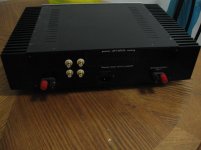
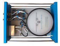
My last little job: Peter Daniel boards with LM3875TF.
Power supply 2 x 120 VA. In plastic box, not interesting to show.
Sounds great.
The little VU-meters (with backgroundlight) are used becouse i had them laying around and they are nice to see, but they are no big deal.
Nice work Danmartin.....
My last little job: Peter Daniel boards with LM3875TF.
Power supply 2 x 120 VA. In plastic box, not interesting to show.
Sounds great.
The little VU-meters (with backgroundlight) are used becouse i had them laying around and they are nice to see, but they are no big deal.
Attachments

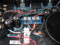
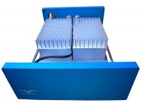
More juice to it!
Hello I just add more juice to my integrated chip-amp.I had two "extra" Mundorf caps. so Now it has 20000uf per channel.The sound is wonderful.
Hello I just add more juice to my integrated chip-amp.I had two "extra" Mundorf caps. so Now it has 20000uf per channel.The sound is wonderful.
Attachments


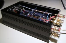
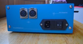
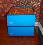
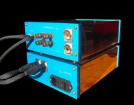
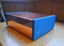
Hi all, my Peter Daniel LM3875 amp.
Copper hood
Aluminum front and back plates and base
Copper feet
Copper hood
Aluminum front and back plates and base
Copper feet
Attachments
-
 R0012363-182.jpg121.7 KB · Views: 2,120
 -
 R0012415-41.jpg221.9 KB · Views: 2,269
 -
 R0012416-42-Edit.jpg126 KB · Views: 2,329
 -
 R0012361-180.jpg136.4 KB · Views: 2,098
 -
 R0012346-165-Edit.jpg144.8 KB · Views: 2,195
 -
 R0012358-177-Edit.jpg130.4 KB · Views: 1,183
 -
 R0012418-44-Edit-Edit.jpg110 KB · Views: 920
Yes all the aluminum is anodized. The front, back and base panels have been bead blasted prior to anodizing.
Hi all, my Peter Daniel LM3875 amp.
Copper hood
Aluminum front and back plates and base
Copper feet
Looks fantastic but you have those lovely heatsinks inside a sealed box????
Frank
Not quite sealed as the base plate is not full width. However if your comment refers to aesthetics - I know they're there.
Not quite sealed as the base plate is not full width. However if your comment refers to aesthetics - I know they're there.
Another "Heatsink in a box" design :-(
(Scotty) You cannne change the laws of physics Jim!
Stereo LM3886 amp
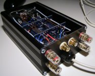
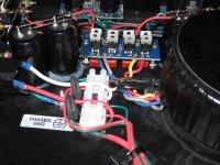
Hi folks.
Long time reader here, so I thought I'd better post pics of an amplifier I made for my girlfriend.
It's housed in an old HP ethernet hub case, and is only 44mm, or 1RU high.
The amp board is designed on the standard non-inverting circuit from the datasheet.
The input and preamp board is loosely based on Rod Elliott's Project 88 preamp, but it includes a speaker mute and fault protection circuit as well.
The transformer is 15+15v, so the amp is only good 15-20w or so, but it's perfect for her loungeroom.
(and to continue the comments above, at such low voltage, this amp only has some angle aluminium and the chassis to cool it. After several hours it only gets a few degrees above ambient...)
I think I spent a maximum of $10 buying actual parts. The rest is the result of years of scrounging bits and pieces, so there's lots of things in there that are glad to be out of various cardboard boxes, and finally doing something useful!
An externally hosted image should be here but it was not working when we last tested it.
An externally hosted image should be here but it was not working when we last tested it.
Great job for $10!!
The whole thing looks well thought out and to do all that on perf board, wow.
Is that a delay circuit in there?
Great job again. You must have other amps. Have you shown us pics of them before? Could you?
Uriah
The whole thing looks well thought out and to do all that on perf board, wow.
Is that a delay circuit in there?
Great job again. You must have other amps. Have you shown us pics of them before? Could you?
Uriah
Well done! I like very much how you get all things toghether!
Congratulations!
🙂
PS: I'm also a "reader" in here... I hope to post pictures soon. Thanks for sharing!
Congratulations!
🙂
PS: I'm also a "reader" in here... I hope to post pictures soon. Thanks for sharing!
- Home
- Amplifiers
- Chip Amps
- Chip Amp Photo Gallery