Thanks ide2003,I was looking for it too but,I did not find a "double pole" rotary switch (safer mode).I will keep looking.
lanchile said:Thanks ide2003,I was looking for it too but,I did not find a "double pole" rotary switch (safer mode).I will keep looking.
What do you switch if you go with double pole? Both neutral and hot?
BTW Mouser has some 6A rotary switches to use. SPDT or DPDT. I'm planning on using these for my next amp, not a chipamp though - Aleph 30 monoblocks.
Yes eboz, I use one for the hot and one for the neutral.I am planning to get a rocket switch and put it where the green light is and the green light where the toggle switch is. http://www.parts-express.com/pe/showdetl.cfm?Partnumber=060-310
Put hazed plex behind the round hole and a LED behind it to light up the hazed plexi to signal when it is on.
So basically the hole would glow whatever color LED you have and be basic White when off.
So basically the hole would glow whatever color LED you have and be basic White when off.
Good idea troystg!.I will start this week.I think I will use blue light better but,I do not want to use led(I do not want to disturb the power supply).so I guess I will put something like blue plexiglass.
How would a LED disturb the power supply?lanchile said:I do not want to use led(I do not want to disturb the power supply)
pacificblue said:
How would a LED disturb the power supply?
That's what I was thinking.. 😉
drop some voltage but where ? because of track length ? if u were talking about dirty soldering tat's because of the flux once it gets cleaned it'll be shiny.
LED will not drop the voltage down, but it is a noisy device, so is not preferred.
It is discussed in one thread. U will have to search for it.
Gajanan Phadte
It is discussed in one thread. U will have to search for it.
Gajanan Phadte
I am sure it can be considered negligible, especially with chipamps which typically have a high PSRR 🙂
LED connection
Another method I've seen for connecting an LED as a power on indicator is to wrap about 25 turns of small gauge wire around the power transformer. Check the voltage and adjust the turns as needed to get below the LED Vforward rating. Connect this directly to the LED and you're done. I haven't tried this, but it sounds quite easy with an open torroid.
My LED is connected to the positive rail, and doesn't inject any noise that I can hear...
" ... Check the voltage and adjust the turns as needed to get below the LED Vforward rating. Connect this directly to the LED and you're done. ..."
This could be quite thrilling if you don't have a voltmeter = checking the AC volts first of course ... a small value cap can protect the LED from the power up surge, a larger cap will make a nice 'fade away" light effect on power off. A daisy chain of diodes, in series, across the fashioned coil with the LED paralleling the last two in the chain will insure proper illumination without the need of regulation ... and to prevent the coil from heating to greatly, the length & number of the diode chain may be increased ... 😉
This could be quite thrilling if you don't have a voltmeter = checking the AC volts first of course ... a small value cap can protect the LED from the power up surge, a larger cap will make a nice 'fade away" light effect on power off. A daisy chain of diodes, in series, across the fashioned coil with the LED paralleling the last two in the chain will insure proper illumination without the need of regulation ... and to prevent the coil from heating to greatly, the length & number of the diode chain may be increased ... 😉
a small value cap can protect the LED from the power up surge, a larger cap will make a nice 'fade away" light effect on power off[/B]
Very true, I've noticed that my LED takes over a minute to go dark. A gentle reminder that bleeder resistors aren't a bad idea, burnt screwdriver tips and exploding caps being the not so gentle reminder... (I built my amp with a traditional power supply)
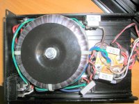
Here's mine
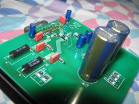
I wanted to build a rugged, small, 30 to 50 watt amp for testing speakers and casual use. Beftus (post 860) and Matjans (post 32) povided the ideas. The schematic is Rod Elliott's
http://sound.westhost.com/project19.htm
and Mick Feuerbacher’s methodology & layout was used to build the circuits http://www.dogbreath.de/Chipamps/GainCardCopy/GainCardCopy.html
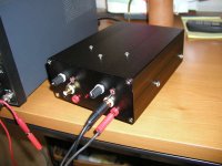
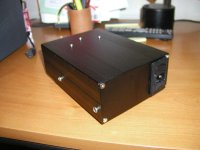
This is a dual channel amp, completely contained in one case about 3" tall, 5 3/4" wide, and 8" long.
I consider myself unbelievably lucky, this amp makes zero noise. No hum, no thumps, ticks, or hiss. I have no sophisticated test gear, just an old used scope and a cheap signal generator, however, the amp's output changes less that a trace's thickness from 20 Hz to about 100 kHz. I'm really pleased with it 😀
I wanted to build a rugged, small, 30 to 50 watt amp for testing speakers and casual use. Beftus (post 860) and Matjans (post 32) povided the ideas. The schematic is Rod Elliott's
http://sound.westhost.com/project19.htm
and Mick Feuerbacher’s methodology & layout was used to build the circuits http://www.dogbreath.de/Chipamps/GainCardCopy/GainCardCopy.html
This is a dual channel amp, completely contained in one case about 3" tall, 5 3/4" wide, and 8" long.
I consider myself unbelievably lucky, this amp makes zero noise. No hum, no thumps, ticks, or hiss. I have no sophisticated test gear, just an old used scope and a cheap signal generator, however, the amp's output changes less that a trace's thickness from 20 Hz to about 100 kHz. I'm really pleased with it 😀
Attachments
Here's mine (3)
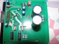
The power supply is a traditional filter bank (although necessarily small). It consists of four 4700 µF caps, 100 v, 35 bridge rectifier & an Antek 200 VA, 22-0-22 transformer. The white rectangles at top of the pic, to the right of the transformer are the loop breaker (Elliott's design) with another 1000V-35A bridge, 10Ù/5W resistor & 0.22 µF 275V MKT cap.
The power supply is a traditional filter bank (although necessarily small). It consists of four 4700 µF caps, 100 v, 35 bridge rectifier & an Antek 200 VA, 22-0-22 transformer. The white rectangles at top of the pic, to the right of the transformer are the loop breaker (Elliott's design) with another 1000V-35A bridge, 10Ù/5W resistor & 0.22 µF 275V MKT cap.
Attachments
- Home
- Amplifiers
- Chip Amps
- Chip Amp Photo Gallery