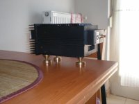
Hey Sanchez! if I were you,I would use a bigger heat-sink for sure!
I hear these LM3886 get hot.I use LM3875 with five times bigger heat-sink then yours and the IC never got hot at all.
it looks nice in acrylic cover,but I would rather use it inside of a metal shield with adequate ventilation.this is just to make sure to eliminate some RF and other interferences .Good luck.
PS: I use a BIG power supply too for my LM3875.belive or not with big power supply they sound way better.I use 10000uf per channel.
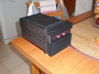
lanchile07 said:Does your amp have fuse?
Back right. It looks like it is a combo IEC socket / Fuse.
Hi Sanchez, looking at the datsheet, I assume some things...
8 ohm load and =-25V suppliy (because you mentioned regulation).
On page 14 you will find the graphs; Power dissipation vs output power.... it shows an average dissipation of 15 to 17W over most of te output power band, and certainly everthing from pushing about 10W output upwards.
Now you may or may not know, that the power rateing for components are normally given assuming a relatively low ambient (air around it) temperature. As the temperature goes up the power that can be delivered decreases and exceeding this margin releases the magic smoke. I.e. if you are able to keep a component cool wile it works,you can push it harder than when you let it carbonise.
I am not interested in safety right now, so lets just aim for survivability. Lets say in summer your ambient temp reaches 30 degrees C. And you would like to keep the heatsink at a max of say 50C. On 25V you could realise about 30W output, and as the graph shows dissipation is pretty non linear (almost flat curve from 10W to max) VS output
So we have to deal with say 17W disspation and we have 50-30 =20C to do it in... wich equals about 1.8C/W, the real number is even lower as the heat of the actual chip die is higher and the flow impeded by the case, thermal paste and isolators...
So maybe 1.3 to 1.5 C /W of dissipation (not output)
Now you can hit an electronic catalog and look for sinks in that range to get an idea of an acceptable size... My guess without looking is about 10x8x5cm, finned.
There are some orange wires anchored to the case that seem to link to earth. Definately an attractive and well designed case 🙂
Nordic said:Its such a wonderfull case, shame its holding a chipamp right now.
Oh well, the road is long and winding.
think I could fit a pair of ucd400's in there?
Nordic said:
Now you can hit an electronic catalog and look for sinks in that range to get an idea of an acceptable size... My guess without looking is about 10x8x5cm, finned.
Hi Nordic,
Thanks very much for your reply. I have to confess that I had not given much attention to the science behind heatsinks, chips, watts, ambient temperature, etc.
I will do my homework and will use the appropriate heatsinks.
Regards
Antonio

heloo. me again, check the pics of portable cmoy built in 40 mins 🙂
http://www.freewebs.com/bego2/cmoyheadphoneampv2.htm
http://www.freewebs.com/bego2/cmoyheadphoneampv2.htm
8-channel LM4780 Amp, Still Under Progress... Some pics
http://picasaweb.google.com/kuldeep1/AudioAmp/photo#5227517446457500898
http://picasaweb.google.com/kuldeep1/AudioAmp/photo#5227517724838131538
http://picasaweb.google.com/kuldeep1/AudioAmp/photo#5227517428050723362
http://picasaweb.google.com/kuldeep1/AudioAmp/photo#5227517679315286354
http://picasaweb.google.com/kuldeep1/AudioAmp/photo#5227517446457500898
http://picasaweb.google.com/kuldeep1/AudioAmp/photo#5227517724838131538
http://picasaweb.google.com/kuldeep1/AudioAmp/photo#5227517428050723362
http://picasaweb.google.com/kuldeep1/AudioAmp/photo#5227517679315286354
Round Gainclone
BrianGT premium, Belden wire, solid brass heat sinks, Noble pot
Case made of 6 inch PVC coupling covered with Mahagony veneer and solid mahagony top and bottom. Top is removeable and vent through copper mesh.
Tranny and PS board in bottom half.
I have enjoyed the sound and like using something I made myself.
http://picasaweb.google.com/Oglesound/RoundGainclone/photo#5234547649522034450
Album
Attachments
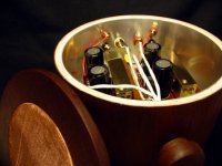

gmilitano- Thanks. The heatsinks are 3 1/2 in. X 1 in. X 3/4 in. and weigh 9 oz. I wanted a low profile high mass heat sink for this design (and I like the way it looks). They are gold plated ground bus bars used in car audio. I bought them surplus from All Electronics. They work very well and I prefer this to finned typed. They never get too hot to touch. With the big opening covered with copper mesh the heat dissipation seems adequate. I've been using this amp daily for 4 years with zero problems. Sounds very nice with my application.
-Ray
-Ray
- Home
- Amplifiers
- Chip Amps
- Chip Amp Photo Gallery