You can try this modified schematic for to get 0 DC at output :
Hi Victor, thanks for your reply.
As i understand, the non-inverting input is held at 3.3/2 = 1.65V. The 220uf cap is there to form a low pass filter to filter out noise of the voltage reference. But what does the 820R resistor at inverting input of lower opamp do?
Also is this implement called I/V? Then as i have read, if we want the Es9018k2m to work in current mode, there must be resistor connecting between +/- output or between +/- output to ground but i haven't seen it.
The lower 820R is providing an offset current so as to bias the output of the lower opamp more positive.
To get current mode its necessary to present a low impedance at the output of the DAC - this is achieved here by virtue of an inverting opamp's 'virtual earth' at its -ve input pin.
To get current mode its necessary to present a low impedance at the output of the DAC - this is achieved here by virtue of an inverting opamp's 'virtual earth' at its -ve input pin.
Hi Victor, thanks for your reply.
As i understand, the non-inverting input is held at 3.3/2 = 1.65V. The 220uf cap is there to form a low pass filter to filter out noise of the voltage reference. But what does the 820R resistor at inverting input of lower opamp do?
Also is this implement called I/V? Then as i have read, if we want the Es9018k2m to work in current mode, there must be resistor connecting between +/- output or between +/- output to ground but i haven't seen it.
Hi,
abraxalito is right - thanks.
As I previously mentioned, the schematic gets 0 DC at output, and it is really working schematic which I am using now in my USB DAC prototype.
To get current mode its necessary to present a low impedance at the output of the DAC - this is achieved here by virtue of an inverting opamp's 'virtual earth' at its -ve input pin.
Sorry, i only have basic knowledge about electronic so can you explain it more in detail? Do you mean that in inverting configuration, the inverting input of opamp is held at virtual ground so the output impedance of the dac is also connected to ground and load it?
The lower 820R is providing an offset current so as to bias the output of the lower opamp more positive.
Does this mean, there will be current flow in to this resistor and it will create a dc voltage at non-inverting input of lower opamp?
Also, i have seen two implement of output stage for es9018k2m, one is a cheap china dac board and it use exactly the recommend output stage for akm dac like ak4490 which is a voltage dac, the other is diyinhk which is simple balanced to unbalanced summing. It seem like both is use for es9018k2m in voltage output mod and create no output offset, why does the dac has output offset when working in current mode?
Sorry, i only have basic knowledge about electronic so can you explain it more in detail? Do you mean that in inverting configuration, the inverting input of opamp is held at virtual ground so the output impedance of the dac is also connected to ground and load it?
Yes, broadly you've got it. The -ve input is held at the same potential as the +ve input due to the large negative feedback factor. Any current sent into the -ve input node from the DAC gets nulled out by the opposite current coming via the feedback resistor from the output.
Does this mean, there will be current flow in to this resistor and it will create a dc voltage at non-inverting input of lower opamp?
No change to the dc voltage at the -ve input (remember its a virtual earth!) but the current induces an equal and opposite current from the output via the feedback resistor.
Also, i have seen two implement of output stage for es9018k2m, one is a cheap china dac board and it use exactly the recommend output stage for akm dac like ak4490 which is a voltage dac, the other is diyinhk which is simple balanced to unbalanced summing. It seem like both is use for es9018k2m in voltage output mod and create no output offset, why does the dac has output offset when working in current mode?
In voltage output it seems there must be a voltage offset (half the DAC analog supply) as the chip doesn't have +/- rails, only +.
Hi all.Is that one?
I see there are one bjt near the power input connect, do you mean it does not have any power regulator design?
Otherwise,
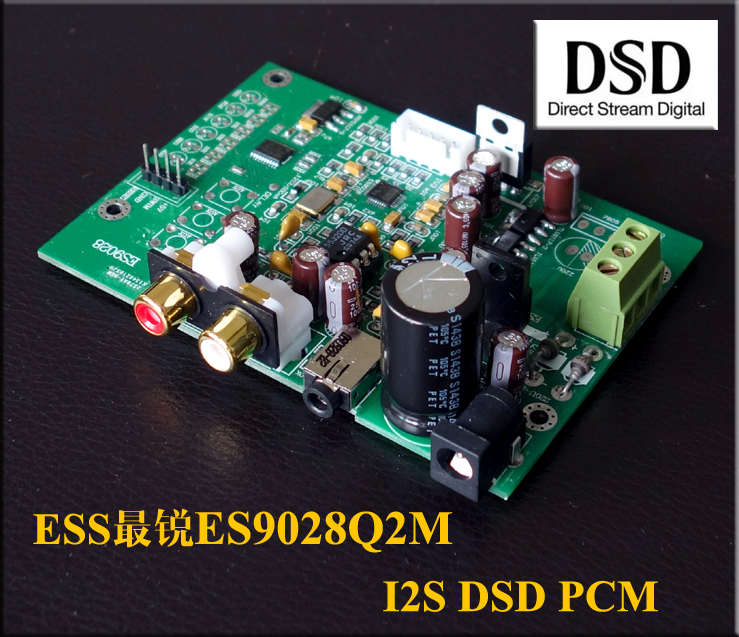
There is their new product used ES9028Q2M:
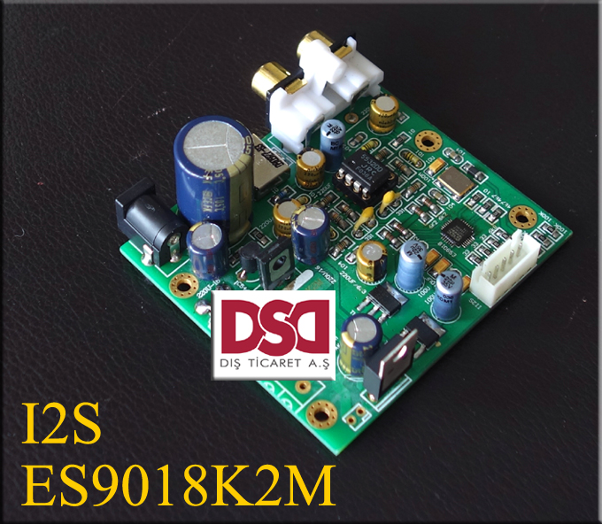
Another shop's design usde ES9018K2M:
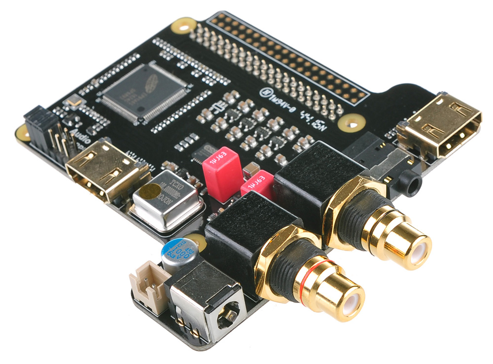
I like the last one design. This products has a kit:
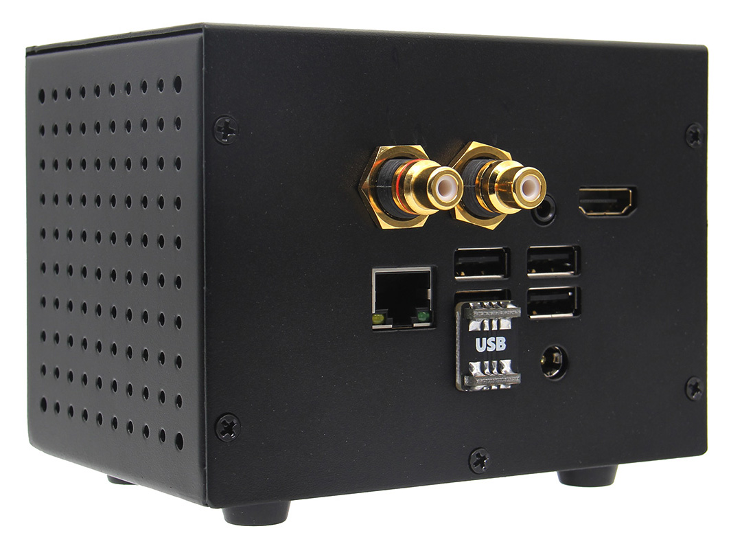
I have order one kit and waiting.....
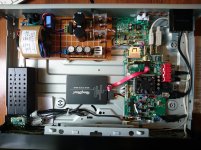
I have used volumio2 fetched from p { margin-bottom: 0.25cm; line-height: 120%; }a.cjk:link { }a.ctl:link { } http://updates.volumio.org/pi/volumio/2.323/volumio-2.323-2017-11-17-pi.img.zip
able to handle with no noise a chinese ES9018K2M shown later:
p { margin-bottom: 0.25cm; line-height: 120%; }a.cjk:link { }a.ctl:link { }
BR
For anyone here to find out about the original question regarding that exact type of ES9018K2M board I found some additional info I was not able to find in this thread nor anywhere else as collected info.
I have I2C volume control up and running on this board thanks to the hifiduino project. The code to fully control the chip over I2C can be found here:
https://hifiduino.wordpress.com/2014/06/13/sw-control-for-es9018k2m/
It took me quite a while to figure out the correct pins on this chip, SCL is pin 3 and SDA is pin 4, they both have a 4k7 pullup resistor to 3.3V that can be tapped easily.
Example to adjust the volume of both left and right channel with Arduino:
What I found with this type of board is that the bypassing caps are placed very badly. This results in a lot of noise being output by the DAC itself and I was unable to solve this. The amplifier noise level when the DAC is disabled (no I2S signal input) is reasonably low i.e. not measurable with a scope and also not audible (with cheap headphones directly on the board output). But as soon as the DAC gets a signal the noise is clearly audible and even visible on a scope. The level I measured is about 80mV (!). Changing the attenuation over I2C does not change the noise level. Also the I tracked the noise to be coming from the BCK signal as it shows peaks at exactly that frequency (5MHz in my case).
With the board not being very well designed I don't think it is possible to get rid of this noise so I ordered a different one, just a little more expensive but way better placement of the digital filter caps. Curious to see if that board performs any better.
I have I2C volume control up and running on this board thanks to the hifiduino project. The code to fully control the chip over I2C can be found here:
https://hifiduino.wordpress.com/2014/06/13/sw-control-for-es9018k2m/
It took me quite a while to figure out the correct pins on this chip, SCL is pin 3 and SDA is pin 4, they both have a 4k7 pullup resistor to 3.3V that can be tapped easily.
Example to adjust the volume of both left and right channel with Arduino:
Code:
void setVolume(byte attenuation)
{
  Wire.beginTransmission(0x48);       //device address
  Wire.write(15);          //volume left register
  Wire.write(attenuation);   //attenuation in dB/2
  Wire.endTransmission();

  Wire.beginTransmission(0x48);       //device address
  Wire.write(16);          //volume right register
  Wire.write(attenuation);   //attenuation in dB/2
  Wire.endTransmission();

}
What I found with this type of board is that the bypassing caps are placed very badly. This results in a lot of noise being output by the DAC itself and I was unable to solve this. The amplifier noise level when the DAC is disabled (no I2S signal input) is reasonably low i.e. not measurable with a scope and also not audible (with cheap headphones directly on the board output). But as soon as the DAC gets a signal the noise is clearly audible and even visible on a scope. The level I measured is about 80mV (!). Changing the attenuation over I2C does not change the noise level. Also the I tracked the noise to be coming from the BCK signal as it shows peaks at exactly that frequency (5MHz in my case).
With the board not being very well designed I don't think it is possible to get rid of this noise so I ordered a different one, just a little more expensive but way better placement of the digital filter caps. Curious to see if that board performs any better.
Hey yall. I had the ess 9028 model of the same board. I dont know if that one comes with an lm317 but mine did. It was a generic. Luckiest thing happenned to me. I put a heatsink on and it snapped off after about a month. Lucky because I had a few st micro lm 317Ts sitting around. Soldered one in, attached heatsink and bleaough boy! The sound became better. It originally had issues around 1hr of continuous use. Those issues all gone. Sound a million times better imho plus in my humble reconstruction from memory. Hope the info helps others. Next great improvement... replacing the crappy generic ne5532 chip that comes with it With a Texas Instruments NE5532. Sounds the other million times better. Now a great unit. I agree 80% volume or certainly <100 sounds best. Im using dc input. Along with an amanero Any thoughts about ac being better? Ive got a massive supply and thing really sounds great with all fixes mentioned
The 15-015 VAC connector is useless. You only have 2 Diodes there (even not perfect for the AC-DC conversion), and just a single reg, so it does not make sense to power the board with a dual voltage trafo. I use the board with a DC of ca. 11V plugged into the round DC plug.
2 diodes is enough for a balanced trafo. Considering it has 3 inputs there inc. neutral that seems lkke the only way. Not much of a filter beyond that. Agree with you there the 9028 filter, or general ac jnput on that cheapest chinese board looks pretty crappy and not able to give my lab psu a run for its money even with a massive balanced trafo. Still wondering if by some miracle it could sound better. Also nervous about connecting to the thing so havent tested yet. Hmmm
I bought the ES9028Q2M Board Again
My first board had the volume issue, it would only output about 8% Volume, i try many things and eventually ended on the trash.
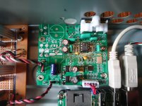
i order the same board again from a different seller on aliexpress, it had the same issue, why would that be.... after many hours of looking around i saw that it was missing a ceramic capacitor like you see on the picture

of course soldering a tiny capacitor like that would be impossible so i decided to bypass it by joining them with soldering wire.
it didn't work.
i try connecting a wire on the third pin of the ST chip and voila... the volume goes up to %100 instantly, but i have to adjust it digitally cuss it sounds distorted.
however every time i turn off the dac it goes back again to 8% volume level. is there a way to fix this issue.
i think on this dac module everything works, it just that i see some modules have this parts missing example:

i saw this guys blog
Oktober 2017 – ES Sabre-90xx-Rpi
he was able to adjust the volume by installing tactile buttons, as you can see he has the ceramic capacitor installed, he then tried installing the RGB lights, but it didnt work, as you can see on the picture he doesn't have the ceramic capacitor on the right side as i do. maybe thats why he wasnt able to make it work.
My first board had the volume issue, it would only output about 8% Volume, i try many things and eventually ended on the trash.
i order the same board again from a different seller on aliexpress, it had the same issue, why would that be.... after many hours of looking around i saw that it was missing a ceramic capacitor like you see on the picture
of course soldering a tiny capacitor like that would be impossible so i decided to bypass it by joining them with soldering wire.
it didn't work.
i try connecting a wire on the third pin of the ST chip and voila... the volume goes up to %100 instantly, but i have to adjust it digitally cuss it sounds distorted.
however every time i turn off the dac it goes back again to 8% volume level. is there a way to fix this issue.
i think on this dac module everything works, it just that i see some modules have this parts missing example:
i saw this guys blog
Oktober 2017 – ES Sabre-90xx-Rpi
he was able to adjust the volume by installing tactile buttons, as you can see he has the ceramic capacitor installed, he then tried installing the RGB lights, but it didnt work, as you can see on the picture he doesn't have the ceramic capacitor on the right side as i do. maybe thats why he wasnt able to make it work.
... you can see on the picture he doesn't have the ceramic capacitor on the right side as i do. maybe thats why he wasnt able to make it work.
Looks like the MCU on that board next to where you put the cap is this one:
https://www.st.com/resource/en/datasheet/stm8s003f3.pdf
From looking at the pinout diagram for the TTSSOP package you should be able to figure out what most or all of the connections are probably for. Also, it may be possible to see where a cap should probably go.
Thanks Mark, ill take a look, already got rid of the distortion...
all i need is just to leave the volume at 100% when turning off the DAC...
For the volume level setting to be preserved there would have to be some nonvolatile memory to save it, and then the MCU firmware would have to write it out either every time you changed it, or if a power down event were being sensed. Unlikely either way. Other settings can be written to flash every time they are changed because they typically don't get changed very often. But, the way some people use volume controls, level changes may be very frequent. Unfortunately, low cost flash ram can only be written a limited number of times, making it hard for a dac designer to know if it would be safe to rely on the memory to save every volume level change. One of the nice benefits of dacs that have pins to connect a volume pot is that a pot can serve as a memory device.
Where this precise volume level of 8% come from? How did you read it?so i decided to bypass it by joining them with soldering wire.
it didn't work.
i try connecting a wire on the third pin of the ST chip and voila... the volume goes up to %100 instantly, but i have to adjust it digitally cuss it sounds distorted.
however every time i turn off the dac it goes back again to 8% volume level. is there a way to fix this issue.
Vcap (pin 8) should be connected to ground with a low ESR capacitor - from 0.47 uF to 3.3 uF, according to the datasheet. 1uF is OK. It should not be shorted!!!
If the code inside the chip doesn't correctly work, you can:
option 1 - use the ESS chip default (100% vol) by removing the I2C command lines: there are two 100R resistor you can see in the picture you have attached - remove them and see what happens.
option 2 - rewrite the code; you will need a ST-Link device/clone (about 2-3 USD), ES9028q2m datasheet (accept the ESS Sabre agreement) and the right programming skills (learn , or find a programmer friend)
Other settings can be written to flash every time they are changed because they typically don't get changed very often. But, the way some people use volume controls, level changes may be very frequent. Unfortunately, low cost flash ram can only be written a limited number of times, making it hard for a dac designer to know if it would be safe to rely on the memory to save every volume level change.
24LC256 is an I2C 256Kb EEPROM with about 1,000,000 erase/write cycles.
If you erase/write it for 100 times a day, everyday, it will save your data over 25 years.
24LC256 is an I2C 256Kb EEPROM with about 1,000,000 erase/write cycles.
If you erase/write it for 100 times a day, everyday, it will save your data over 25 years.
Cheap Chinese dacs like the one we were just talking about in this thread don't use them. Only what is in the very low-cost MCU, and most of those that have internal EEPROM have pretty limited number of write limits, IIRC.
Agreed, there much better nonvolatile devices available.
Last edited:
Where this precise volume level of 8% come from? How did you read it?
Not precisely 8%, i don't have the tools to measure the output level.
i did took out the 100R resistors, nothing happen.
its weird how this thing works, i have to make contact with the pin on the ST chip to the soldered part with a metal pin a few times and the volume goes to 100%, its a process kinda like turntables... XD
its just a cheap board, nothing serious... i will eventually start reading The Art of Electronics: Paul Horowitz and learn a few things from here and different sources as well.
im not an electronics experts, just a web & Graphic designer.
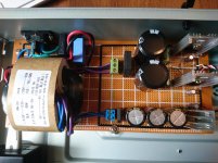
Refined food opa2134 feeds + \ - 15v
I hesitate to ask, and the circuit of the power supply and the circuit Board 3.3 volts can put? I see on the Board native Soviet resistors are🙂.
What budget-ish usb to i2s board would you recommend to go with one of these generic ES9028Q2M boards these days? I have a cheap PCM2706 one currently for another dac build, but I'd like to get something more modern for a new setup.
- Home
- Source & Line
- Digital Line Level
- Chinese ES9018K2M I2S DAC