Noob: How to confirm drivers are in phase.
Hello, Guys. First post.
I built a WWMTM 3-way kit system many many years ago. Over the years, I've "upgraded" the 1st order crossover components, and replaced the woofers. The woofers are not what was originally designed into the system. They sound OK after a lot of EQ tweaking with the AV receiver. But it's really a miss-mash at this point. I intend to rebuild them. I'll keep the Peerless woofers I've got, replace the midranges with some SBA units, and rebuild the Morel tweeters.
I've spent hundreds of hours with Jeff Bagby's Passive Crossover Designer 8.0, and Response Modeler 3.01. And I've spent as much time on the web browsing through forums, like this, and tutorials, and examples, trying to get my arms around the fundamentals of crossover design. I will probably end up with a 2nd order LR low cross, and a 4th order LR / 2nd order LR high cross.
This is probably just a one time deal. I'm not going to be building a bunch DIY systems, though I do understand the appeal. I do not have test equipment, so I'm forced to do the best I can with manufacturer's data and available modeling software, and my ears.
I've come a long way, but I'm a bit befuddled by phase plots, and how to insure the best system phasing I can. I understand the concept of phase and time alignment, but when I look at phase plots, all I see are a bunch of lines all over the place. I can model a nice linear RF, and flattish system impedance. I can achieve deep reverse nulls at the X-points. But how do I know when I have best overall system phasing I can get (given my limitations)? When using Jeff's PCD 8.0 and I overlay phase plots with FR plots, what should I be seeing? Do you have some examples?
Please ask me whatever you need to.
Thanks in advance, Steve
Probably TMI in my original post....
I'm developing a 3-way system using Jeff Bagby's PCD 8.0. I'm using 2nd order LR slopes, with possible exception of the low pass on the midrange going to 4th order LR to avoid cone break-up. Other than confirming deep reverse nulls at the crossover points, when switching the wiring of the midrange, how do I confirm good overall system phasing, using the PCD software?
Thank you
You can see that the phase of each driver has the right relationship over the crossover region. In other words the band of frequencies where the other driver is not so quiet that it has almost no input, for example a couple of octaves.
When it is unclear what the relationship should be, people default to lining up the phase. This is what I would advise at the moment.
I'd first question whether you can trust the phase plots you are working with..
When it is unclear what the relationship should be, people default to lining up the phase. This is what I would advise at the moment.
I'd first question whether you can trust the phase plots you are working with..
Thanks, Allen
When you say "You can see that the phase of each driver has the right relationship over the crossover region". What precisely do you mean. The summed responses I've developed are pretty linear, and 6db above at the crossover points. And the individual driver responses look pretty good.
"...people default to lining up the phase. This is what I would advise at the moment". Exactly. That is what I'm asking about. How do I do that? What am I looking for in the plots? I'm constantly checking reverse nulls as I move things around, which correspond with intersections of the individual driver phases plots. But I think this doesn't necessarily insure good overall system phasing. Or am I wrong on that?
"I'd first question whether you can trust the phase plots you are working with.." You're right. I assume Jeff Bagby's PCD 8.0 is reasonably accurate, but only as good as the information I am inputting. I do not have the test equipment to gather my own data, so relying on manufacturer's data and curve scanning software for the FRD and ZMA files. Making educated guesses at the Z offsets. And using JB's Response Modeler 3.01 for box alignment, baffle step, diffraction compensation, minimum phase extract, etc.
The standard first order crossover has a 90 degree difference between the phase of each driver, at each frequency. What you are looking for is that this happens over a wide enough range of frequencies. This means that the slope of the phase plot for each will match, which is usually what you want.
Let me know if you want examples.
Let me know if you want examples.
I am a visual learner, so examples would be great. Remember this is a 3-way with 2nd order Linkwitz-Riley slopes. (Possible 4th order at Midrange low pass). Midrange is reversed.
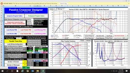
I've attached one of the systems here. This happen to have the 4th order midrange low pass, due to the minor cone breakup at 10,000K. (I've either got to use a 2nd order with LCR or 4th order). Target X-points are 300, and 2400 in this example.
I've attached one of the systems here. This happen to have the 4th order midrange low pass, due to the minor cone breakup at 10,000K. (I've either got to use a 2nd order with LCR or 4th order). Target X-points are 300, and 2400 in this example.
Attachments
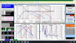
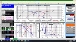
Ok, good example. Look at the first plot (the null plot is of no interest).
Look at the bandpass phase (pink plot) and tweeter phase (orange plot). They stay together mostly. At 900Hz, they are only 30 degrees apart, and at that point the tweeter is more than 20dB down. It got out of the way before phase departed and that is useful.
Now look at the top end. The phase plots deviate in slope above 3kHz when the drivers are still working together, as they are 8dB apart. It isn't too bad in this case but this is the first thing to look for.
Thanks, Allen
Big help. Exactly the type of input I was looking for. I'll work with this a bit. I'll need to get a feel for what and how to adjust the components to bring the phase plots together, while maintaining a viable summed response.
Big help. Exactly the type of input I was looking for. I'll work with this a bit. I'll need to get a feel for what and how to adjust the components to bring the phase plots together, while maintaining a viable summed response.
Here's something that might help, in addition to what Allen has said.
https://www.rationalacoustics.com/download/Smaart-v8-User-Guide.pdf
Go to page 117, about comparing phase traces. You'll probably then want to read a few prior pages too.
It's about reading phase measurements, but the same alignment principles apply to calculators/simulators.
https://www.rationalacoustics.com/download/Smaart-v8-User-Guide.pdf
Go to page 117, about comparing phase traces. You'll probably then want to read a few prior pages too.
It's about reading phase measurements, but the same alignment principles apply to calculators/simulators.
Thank you, Mark100. Good stuff. I've done so many searches on reading phase plots, and never found anything as clear as that tutorial. Great help.
Steve,
how did you arrive at the phase data of the drivers used, by measuring yourself or by having calculated minimum phase of each?
how did you arrive at the phase data of the drivers used, by measuring yourself or by having calculated minimum phase of each?
Thank you for the question. I have no means of measuring myself, so I've used the manufacturer's data. I know some here will say that is a deal breaker, but I've got to do the best I can with what I've got, and assume the manufacturer's data is reasonably accurate. I've done quite a bit of research on line, in an attempt to make some reasonably good choices. I used an available on line graph tracer to create the initial ZMA and FRD files from manufacturer's curves. I applied that information first to Jeff Bagby's Response Modeler 3.01, to get box alignment adjustment, baffle step and diffraction adjustments, and Minimum Phase adjustment to the ZMA and FRD files. Then applied those modified curves to Jeff Bagby's Passive Crossover Design 8.0.
There is a couple of things to do to improve the sim a little bit. If you haven't already, have the phase calculated by FRD Response Blender and Minimum Phase Extractor where you can adjust the tails of the FR so the calculated phase is more precise than what you would get out from Response Modeler. Secondly, you have applied the Z offset to the woofers as positive 3cm, instead of negative 3cm, because such is the convention in PCD, unlike XSim, assuming your woofer's acoustic centre is farther than tweeter's. Then you have not specified the Y offset of the drivers (reads zero).
It's not a deal breaker, it will get you close.
However taking non-minimum phase information and converting it to its apparent minimum phase equivalent is taking correct information and making it incorrect.
However taking non-minimum phase information and converting it to its apparent minimum phase equivalent is taking correct information and making it incorrect.
Thank you Lojzek,
I'm glad you brought up the Y offset. Mr. Bagby's Response Modeler3.01 has X and Y offsets as well. It has you define the box, baffle dimensions, and driver placements. In sequence it has you apply the box response to the original FR and Imp curves, then the baffle step correction and edge diffraction, then the Minimum Phase Extractor. My assumption was that once that's done in Response Modeler, and you transfer the resultant FRP and ZMA files to PCD, the X and Y offsets shouldn't be input, as PDC would reapply that information to files that already have that embedded in the results. There was no instruction regarding this in either program. Is my assumption incorrect?
I'm glad you brought up the Y offset. Mr. Bagby's Response Modeler3.01 has X and Y offsets as well. It has you define the box, baffle dimensions, and driver placements. In sequence it has you apply the box response to the original FR and Imp curves, then the baffle step correction and edge diffraction, then the Minimum Phase Extractor. My assumption was that once that's done in Response Modeler, and you transfer the resultant FRP and ZMA files to PCD, the X and Y offsets shouldn't be input, as PDC would reapply that information to files that already have that embedded in the results. There was no instruction regarding this in either program. Is my assumption incorrect?
However taking non-minimum phase information and converting it to its apparent minimum phase equivalent is taking correct information and making it incorrect.
Thank you, Allen. Can you help me understand this? Are you saying I should not be using Response Modeler, or at least its Minimum Phase Extraction function, before loading to PCD?
It's about using the right tool at the right time. Again, it's not a deal breaker but I wouldn't do this with an important speaker.
Say you have an impulse that includes both minimum and non-minimum components with a response magnitude. If it is converted to a frequency response plot, that timing information is lost and nothing can be 'extracted'. Due to the incorrect usage of the term, it has become an audiophile myth that you can extract whenever you want, when it may actually add (partially) incorrect information.
So, there are two times when this is normally done. Getting minimum phase for a factory plot that has none, is fine. The other is when incorrect measurement methods are used and it's a band-aid method to reset the timing element.
If you start with minimum, then use a reputable diffraction simulator.. then don't re-run minimum on it.
I apologize, Allen. I'm still missing something in the explanation. I am starting with factory plots, and then following Bagly's instructions carefully on how to go through the functions in Response Modeler. So I'm not clear on where my error is. I guess I was hoping to get closer to real world data, by going through RM. Is that unrealistic? Is the problem just with the Minimum Phase Extraction function in RM? Are the box alignment and baffle compensation part of it OK to use? Not arguing. I really appreciate that you are taking the time to help me out. Just trying to understand.
- Home
- Loudspeakers
- Multi-Way
- Checking phase alignment for 3-way crossover