Thanks, Jerms.
I would like to have a gain of 26 dB. 20 dB would be low for me as I use an unity buffer before the TPA3118 amp.
I suggested the simplest approach.... for a level of "simple" involving SMD soldering. 🙂
26dB requires replacement of components, rather than simple removal. The combinations are in the TPA3118 or TPA3116 topics.... Known needle in two haystacks....
You'd be better off ordering the "official" Sanwu boards and comparing them to the ones you have. Or modifying the current ones and comparing them to the unmodified Sanwus when they arrive.
In direct comparison, i'd say this chip is genuine TI, but not a TPA3118, it's a blacktopped TPA3130. 

TPA3118: $1.45/1k
TPA3130: $1.05/1k
The TPA3130 is the low power TPA3118 (2x15W). Could you try acetone on the surface and scratching with your fingernails?
TPA3118: $1.45/1k
TPA3130: $1.05/1k
The TPA3130 is the low power TPA3118 (2x15W). Could you try acetone on the surface and scratching with your fingernails?
Last edited:
Let's see if he may proove this by acetone and scratching. I also ordered 2 of them yesterday.
The thing is, the TPA3130 have it's OC-trippoint set at 4.5A. As we go PBTL (double OC current), this ain't an issue as these inductors aren't able to handle even 4.5A without unlinearity/distortion.
The thing is, the TPA3130 have it's OC-trippoint set at 4.5A. As we go PBTL (double OC current), this ain't an issue as these inductors aren't able to handle even 4.5A without unlinearity/distortion.
Let's see if he may proove this by acetone and scratching. I also ordered 2 of them yesterday.
The thing is, the TPA3130 have it's OC-trippoint set at 4.5A. As we go PBTL (double OC current), this ain't an issue as these inductors aren't able to handle even 4.5A without unlinearity/distortion.
@doctormord, do you mean I should rub the top of the chip with acetone to try and see if I can rub off the print? And reveal more writings below?
After rubbing vigorously with acetone, using both a piece of tissue paper wetted in acetone and finger nail. Nothing comes off. The piece of tissue doesn't collect black deposit, which I presume it would have if it was rubbing off a coat of "black topping". The only change I see is the printed text has become fainter due to the rather vigorous ministrations.

The new scratch mark is where I accidentally scratched it with the tip of a screw driver.
Now, back to regular programming:
1/ how do I change gain to 26 dB? I'm ready to de/solder SMD resistors to achieve it.
2/ where exactly do I put those 330 pF + 10R?
I'll appreciate pointers for the above two queries.
Well yes, could also be the other way around, not blacktopped but shaved down (as irribeo stated earlier) Both ways are common practice to apply new markings.
Maybe i get the same "3118" to further investigate. Nothing's wrong with the 3130, it's just limited by design to a lower current. Maybe thats a degraded 3118 to get a higher yield from the wafer.
So now back to topic. 🙂
Maybe i get the same "3118" to further investigate. Nothing's wrong with the 3130, it's just limited by design to a lower current. Maybe thats a degraded 3118 to get a higher yield from the wafer.
So now back to topic. 🙂
Last edited:
For me the simplest option is still "remove R27". It doesn't cost anything assuming SMD soldering skills are up to it. Then listen to it again to review background noise levels.
It that works, then maybe consider the 26dB component changes.
It that works, then maybe consider the 26dB component changes.
Might be that the output filter is "ringing" due to 8R speaker, so this can lead into this harshness.
Many OT posts removed. I would recommend you take your OT discussions to private email.
Also
and  are reserved for moderator use only.
What value of inductor would be appropriate for 8 Ohm load? The current inductors are labeled "100". Is that 100 uH?

Also got those boards. As people recommend remove R27. This will lower the gain to 20dB because R2 (R27) is open. If you want 26dB you need to place 100k ohm on R2 (R27) and 20k ohm on R1 (R28)
Just removing R27 is by far the easiest.
In direct comparison, i'd say this chip is genuine TI, but not a TPA3118, it's a blacktopped TPA3130.
QUOTE]
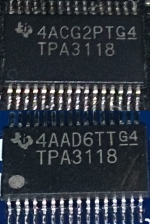
Because picture was removed and some might want to compare how two 3118 look like, top genuine Texas Instruments tpa3118, bottom genuine something else, counterfeit I would say, the G is different and logo is too.
Attachments
This Tpa3118 chip seem to look like the ones Texas Instruments makes
Also got those boards. As people recommend remove R27. This will lower the gain to 20dB because R2 (R27) is open. If you want 26dB you need to place 100k ohm on R2 (R27) and 20k ohm on R1 (R28)
Just removing R27 is by far the easiest.
This Tpa3118 chip seem to look like the ones Texas Instruments makes
They were dirt cheap on ali. Sound good. Added 1000uF to power terminal.
Inductors look a little sloppy and 33uH probably better match your speaker, 22uH would if you also replace the 1uF largest ceramic next to the inductors.
Im not very keen on desoldering and soldering those small ceramics. Would rather change the inductors. I have no clue which kind of inductors to use. There are the wurth ones on ebay but they are very expensive for such a cheap board. What about these 20% 0.06Ohm 3A SMD Power Inductors CDRH127 33uH 12mmx12mmx7.2mm 10 Pcs | eBay
No Conrad or other a little more reliable distributor than Alie or Ebay in Denmark ?
Oh and maximum size that will fit is 10x10mm
Oh and maximum size that will fit is 10x10mm
- Home
- Amplifiers
- Class D
- Cheap TPA3118D2 boards, modding them and everything that comes with it