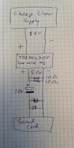
Hi again, So I finally got round to making the tests yesterday evening. Included the back-to-back diodes, after the cap across the line input. Turns out my cheap multimeter is very imprecise at low voltages and it did look as if there was a very small DC offset of about 200mV, despite the cap, across the pins, but I went ahead.
I wired a couple of 10R resistors, in parallel across the 5V output as a load.
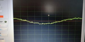
The improvement when including the TPS7A4700 Ultralow-noise (4µVrms) regulator was dramatic.
I did try cleaning up even more, using an LC filter marketed for Quadcopters, but the result didn't look as good, so I removed it.
It should also be mentioned that I connected all the stages together using solderless project board (breadboard), and trying to repeat some of the tests resulted in much worse results, so I don't trust the integrity of the connections or the exact results, but in all cases, the TPS7A4700-filtered power was cleaner than anything I got straight from the power supply.
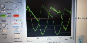
I have no idea of the levels, as I don't have anything that generates frequency of a known amplitude. All I can say is that a "Thumb test" was significantly noisier than any of the power supply tests.
I am going to further improve the supply with a pre-built capacitance multiplier ("Allo"), next week, but have already powered up my new, topping D50s, using the supply and notice a clear improvement (much more clarity) over the S.M.S.L Sanskrit Pro I had before.
Thanks all for your help and suggestions!
I wired a couple of 10R resistors, in parallel across the 5V output as a load.
The improvement when including the TPS7A4700 Ultralow-noise (4µVrms) regulator was dramatic.
I did try cleaning up even more, using an LC filter marketed for Quadcopters, but the result didn't look as good, so I removed it.
It should also be mentioned that I connected all the stages together using solderless project board (breadboard), and trying to repeat some of the tests resulted in much worse results, so I don't trust the integrity of the connections or the exact results, but in all cases, the TPS7A4700-filtered power was cleaner than anything I got straight from the power supply.
I have no idea of the levels, as I don't have anything that generates frequency of a known amplitude. All I can say is that a "Thumb test" was significantly noisier than any of the power supply tests.
I am going to further improve the supply with a pre-built capacitance multiplier ("Allo"), next week, but have already powered up my new, topping D50s, using the supply and notice a clear improvement (much more clarity) over the S.M.S.L Sanskrit Pro I had before.
Thanks all for your help and suggestions!
Attachments
Last edited:
Slightly off-topic and before I add the cap. multiplier. I believe I should protect the TPS7A4700 against reverse voltage; would this
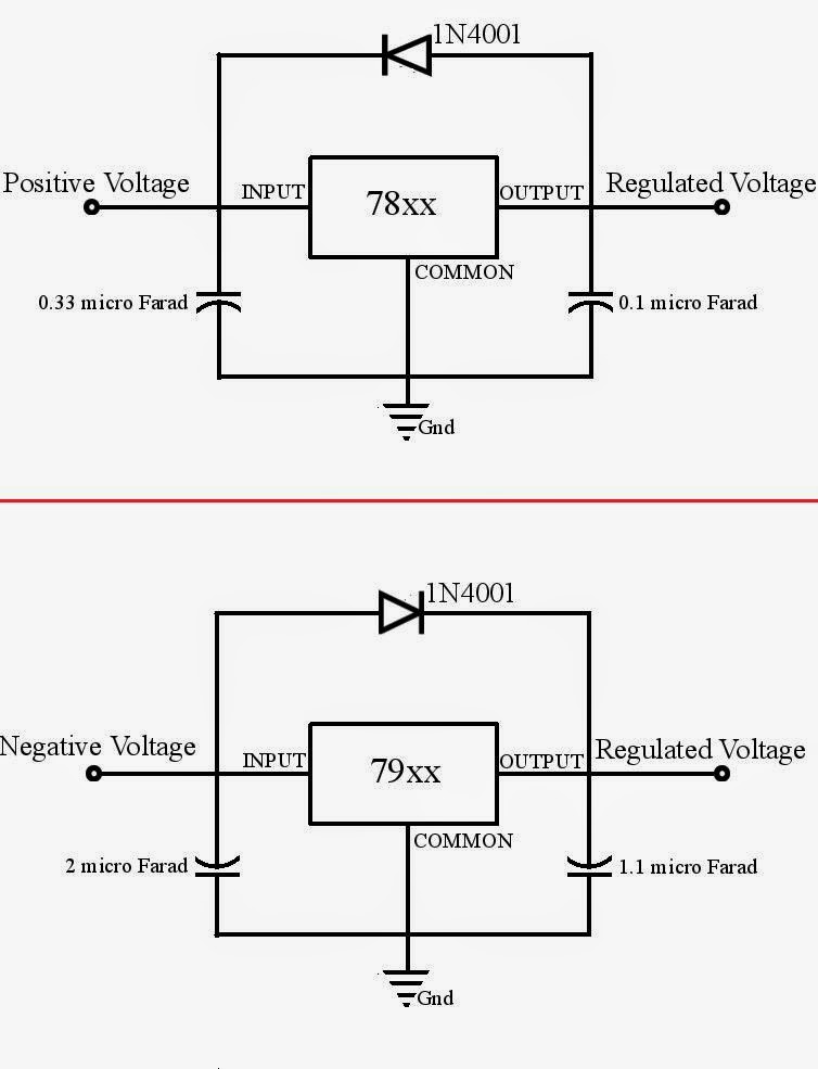 be the best arrangement?
Use of "large" caps after the regulator might preserve voltage on the output side after the input voltage dies. Apparently that can kill the TPS7A4700. A "+" to "+" Diode across the regulator (top graphic) would short back to the input side when output side voltage is higher.
Not sure of the function of the caps 😉
Not sure of the function of the caps 😉
Last edited:
Member
Joined 2009
Paid Member
And if you can't hear it...
headphones are very sensitive and although I didn't try it myself I suspect it's a good option. Of course, nothing like a new 'scope to play with.
This week I discovered my PS noise problem was not due to insufficient filtering.
It was proximity to the analog sections of circuit.
The emi was radiated from ps module.
CISPR 25 is the commercial test standard but you can use a battery powered AM radio and get similar test results.
-
It was proximity to the analog sections of circuit.
The emi was radiated from ps module.
CISPR 25 is the commercial test standard but you can use a battery powered AM radio and get similar test results.
-
- Status
- Not open for further replies.
- Home
- Design & Build
- Equipment & Tools
- Cheap oscilloscope solution for measuring power supply noise