Oh good thinking! I'll do that too.unfortunately, I am not at home with my computer right now. That's where all my pictures are.
Half way around the earth actually! Planning to get back in early September.
But, a simple sim with HornResp will give you all the info you need. And for the MA driver, I followed X's suggestion from his other design and used a sports cone to isolate it from the line.

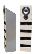
I like that! Would be interested to see a diagram of the cabinet design.
I probably will make mine even slimmer. I want it to look aesthetically sort of like some of the small totem towers
I will check out hornresp
Last edited:
would be hard to make it slimmer... you do need a little breathing space for the woofer. That's about how slim I would go, with wall thickness and al.
HornResp is amazing, but it takes a bit of learning before you get the hang of it. We all did, so can you.
HornResp is amazing, but it takes a bit of learning before you get the hang of it. We all did, so can you.
SB Acoustics all the way!
To anyone:
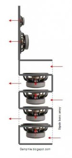
Is there any disadvantage to laying out a SLOB configuration tilted 90° as shown in the image below? I am thinking that this layout would work better if one were to do a racetrack driver SLOB, to save space vertically, but if there are any drawbacks sonically I'm unaware of them. Does anyone know if there is?
Thanks!
Edit: after some quick math, the space saved vertically would be negligible, but I'd still be interested to know in any sonic differences you might get from configuring a SLOB speaker in this way. Also, I found out the example I pictured isn't even a SLOB haha
Attachments
Last edited:
Is there any disadvantage to laying out a SLOB configuration tilted 90°
Gravity. Most drivers are designed for moving free of gravity. Rotate them so they are firing vertically and your are into unbalanced and non-ideal territory.
Theres a formulae for working out the immediate sag for a woofer mounted firing up/down
https://www.parts-express.com/woofer-mount-up-down
But this doesnt account for any possible time effects on woofer suspension creep. Every time the woofer approaching Xmax there will be an unbalanced excursion downwards. Who knows how this affects the suspension of a woofer model but speculation would say it cant be good. If the woofers are a pair firing up/down they could be swapped regularly to even out any longer term creep. But who would do that?
Better to mount horizontally.
I didn't even think about that. Silly me. Everyone on this site is so clever lol. Thanks for your input!Gravity. Most drivers are designed for moving free of gravity. Rotate them so they are firing vertically and your are into unbalanced and non-ideal territory.
Theres a formulae for working out the immediate sag for a woofer mounted firing up/down
https://www.parts-express.com/woofer-mount-up-down
But this doesnt account for any possible time effects on woofer suspension creep. Every time the woofer approaching Xmax there will be an unbalanced excursion downwards. Who knows how this affects the suspension of a woofer model but speculation would say it cant be good. If the woofers are a pair firing up/down they could be swapped regularly to even out any longer term creep. But who would do that?
Better to mount horizontally.
Everyone on this site is so clever
if you follow what xrk does you can save countless issues
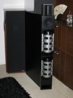
I am moving forward with conceptualizing a basic design for the SB racetrack speaker in a SLOB configuration idea. I don't have the resources to build it any time soon, but I am having fun working out some of the kinks on paper. I thought I'd share my work (achieved by following X's instructions) to potentially help anyone else designing their own SLOB. Also, please correct any flaws in my work if you find any. Thanks! It's pretty simple stuff, so that would be embarrassing, but ya never know!
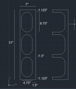
X says that the cross sectional area of the slot should be 1/3 of the combined sd of the drivers used. The SB racetrack has an sd of 178cm^2, for a combined Sd of 356cm^2. We divide this figure by 3: 356/3=118 and 2/3.
I'm struggling to phrase how to describe a racetrack woofer, so for this 5"x8" SB woofer I will call the 8" side the long end and the 5" side the short end (the actual outside diameter is 253mm x 153mm, the 5x8 figure more closely describes the dimensions of the radiating surface)
We are mounting these drivers such that the long end extends vertically and the short end extends horizontally. This decreases slot depth, which increases the upper bandwidth of this configuration. I actually am not sure of the formula for this bandwidth calculation, but I'm sure someone can fill in that blank
Because we are mounting the long side vertically, we must have a slot height of at least 8.75", which is the length between the ends of the surrounds.
8.75 inches = 22.225cm
118.66 (1/3 of combined Sd) divided by 22.225 gives us 5.34cm (2.102362 inches)
So, the cross sectional area for our SB racetrack slot is 8.75"x2.1". Since MDF is not available in tenths of an inch, I will be extending this width to 2.125" (one 5/8" MDF board and two 3/4" MDF boards. I am just following X's instructions, so I don't know the consequences of this, but it is such a small divergence that I am sure it won't hurt
Hopefully this helps. Info on this type of speaker seems sparse, so I felt compelled to add to the shallow pool, even if I am just reiterating the ideas of X
Last edited:
SB Acoustics SB15SFCR39 slot enclosure design. Since the 5x8" figure does not represent the actual width of the driver, I currently have a slot depth of 5.5". Plus the baffle, I'll be sat at around 6.25" if I go for a 3/4 inch baffle. By the way, would there be any consequence to reducing the baffle width? My mid range and tweeter will basically be sitting on top of my SLOB, so it will be on a different baffle, so the bass baffle won't exactly be doing much in terms of maintaining structural integrity I don't think?
Attachments
Last edited:
Looks good Bryguy. The slot depth controls the upper cutoff frequency based on the 1/4 wave cancellation. So a 5.5in slot depth is 0.0254m/in x 5.5in / 342m/sec x 1/4 = 616Hz upper cutoff bandwidth. So you should set your crossover electrical filter to match this to get a free 4th order low pass for the price of a 2nd order electrical.
Thanks X! And that is good to know regarding the upper bandwidth formula. For the bass region I will be using digital filters, so the cost is all the same for me!Looks good Bryguy. The slot depth controls the upper cutoff frequency based on the 1/4 wave cancellation. So a 5.5in slot depth is 0.0254m/in x 5.5in / 342m/sec x 1/4 = 616Hz upper cutoff bandwidth. So you should set your crossover electrical filter to match this to get a free 4th order low pass for the price of a 2nd order electrical.
Good to know!Still, the intrinsic filter is at 616Hz, why not use it? The phase wrap of higher order electrical filters is also something to avoid.
- Home
- Loudspeakers
- Full Range
- Cheap and FAST OB, Literally