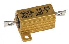
I often use the chassis to heatsink semiconductors via some sort of aluminium heat spreading/coupling system, when in doubt about performance I mount a aluminium housed wire wound resistor on the the thermal coupler powering it from my bench top power supply with a known wattage for a couple hours so the temperature rise above ambient can be measured and the system can be parameterized.
Attachments
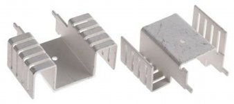
I god some of these, maybe will fix them on top. Decisions, decisions...
Attachments

If a heat sink is horizontal, convection will not create airflow between the fins.
Pin-fin heatsinks work better in this application where the heat sink is horizontal. Without a fan, wide spacing between the pins is preferred. You can get them for cheap as "LED heat sink" on aliexpress.
Pin-fin heatsinks work better in this application where the heat sink is horizontal. Without a fan, wide spacing between the pins is preferred. You can get them for cheap as "LED heat sink" on aliexpress.
Attachments

Last edited:
I've ordered material from this place to make both sides panels into heatsinks with the 10 inch wide material, I had them cut off two pieces 2 inches in length. Fins then go vertical. but I have wood sides so was able to work in the aesthetics and trim. For any pc boards I make I always locate the TO220 and TO247 devices at the board edge so boards just bolt to the side panel heat sinks. I drill and tap blind holes so no screw heads showing from outside and no nuts needed. Their website is very slow but works, 30 seconds per page load, its probably a server in their basement!
Extruded Aluminum Heatsinks from HeatSinkUSA
10.000" Wide Extruded Aluminum Heatsink - HeatsinkUSA
Extruded Aluminum Heatsinks from HeatSinkUSA
10.000" Wide Extruded Aluminum Heatsink - HeatsinkUSA
I've ordered material from this place to make both sides panels into heatsinks with the 10 inch wide material, I had them cut off two pieces 2 inches in length. Fins then go vertical. but I have wood sides so was able to work in the aesthetics and trim. For any pc boards I make I always locate the TO220 and TO247 devices at the board edge so boards just bolt to the side panel heat sinks. I drill and tap blind holes so no screw heads showing from outside and no nuts needed. Their website is very slow but works, 30 seconds per page load, its probably a server in their basement!
Extruded Aluminum Heatsinks from HeatSinkUSA
10.000" Wide Extruded Aluminum Heatsink - HeatsinkUSA
I have a question....
Unless I'm missing something, I've been on that website and for the life of me I cannot find out the actual length of the fins for each product.
I know length of a heatsink, and fin heights listed, but where on earth is the fin lengths?
Specifically, if you measure along the top of one fin.
For instance, If I were to mount one on the back of a 3" high amp chassis, and not exceed that height, fins vertical.
Here is an amp I did last year, the fins are 2.5" high on a 3" rear panel.
Attachments

Last edited:
I have a question....
Unless I'm missing something, I've been on that website and for the life of me I cannot find out the actual length of the fins for each product.
I know length of a heatsink, and fin heights listed, but where on earth is the fin lengths?
Specifically, if you measure along the top of one fin.
For instance, If I were to mount one on the back of a 3" high amp chassis, and not exceed that height, fins vertical.
Here is an amp I did last year, the fins are 2.5" high on a 3" rear panel.
For a piece of the 10 inch material they told me the fin height is 96 inches, 8 feet. Their stock comes in 8 foot lengths from the aluminum extruder supplier. So when they cut off a 2 inch long piece for me, the fin height is 2 inches, the width of the stock is a fixed 10 inches. So a 2 inch piece gives you a row of vertical fins 2 inches high, spread out 10 inches by whatever the fin interval is, I think about 8mm or so. They also have 8 inch stock. I'm not sure if this answers your question. 🙂
Here is a good source of information on heat sinks. I used AAVID as a source for many years when I was a design engineer.
https://info.boydcorp.com/hubfs/Resources/Resource-Center/Boyd-Guide-to-Heat-Sink-Fabrications-2020-Technical-Paper.pdf
Page 9 here gives a good example of how to calculate heat dissipation in a heat sink Same company as above, AAVID.
https://www.mouser.com/pdfdocs/Aavid-Board-Level-Heatsinks-Catalog.pdf
Last edited:
For a piece of the 10 inch material they told me the fin height is 96 inches, 8 feet. Their stock comes in 8 foot lengths from the aluminum extruder supplier. So when they cut off a 2 inch long piece for me, the fin height is 2 inches, the width of the stock is a fixed 10 inches. So a 2 inch piece gives you a row of vertical fins 2 inches high, spread out 10 inches by whatever the fin interval is, I think about 8mm or so. They also have 8 inch stock. I'm not sure if this answers your question. 🙂
I'm still a bit confused.
Look at the rear view amp I posted.
See the vertical dimension is 2.5 inches high, and it's 6 inches long.
The 2.5 inch dimension of mine, is what I'm talking about.
It's not clearly described on that website's charts.
I understand the lengths, and the fin extension from the plate, just not how wide the fins are.
Very interesting reading, thank you! Some of my radiators came from that company, AAVID.Here is a good source of information on heat sinks. I used AAVID as a source for many years when I was a design engineer.
https://info.boydcorp.com/hubfs/Resources/Resource-Center/Boyd-Guide-to-Heat-Sink-Fabrications-2020-Technical-Paper.pdf
Page 9 here gives a good example of how to calculate heat dissipation in a heat sink Same company as above, AAVID.
https://www.mouser.com/pdfdocs/Aavid-Board-Level-Heatsinks-Catalog.pdf
Attachments
Keep in mind the PEAK screen currents which can be present - and can (on a cycle by cycle basis at clipping) go way up beyond 20 mA per tube. It has been known to cause mosfet regulators to fail unexpectedly. The heat sink heats up based on the average power. The transistor needs to be able to take the peak current, at the VDS voltage, at the temperature the heat sink gets to. This is a good reason to keep the temperature LOW, even if simple math based on average dissipation would let you get away with 125C case temp. Short duration 100 mA peaks per valve are not uncommon. At 100 volts that’s 10 watts (each), 20 per pair. Modern mosfets sometimes have trouble with 20 watts at 100 volts, and it only gets worse with temperature.
I'm still a bit confused.
Look at the rear view amp I posted.
See the vertical dimension is 2.5 inches high, and it's 6 inches long.
The 2.5 inch dimension of mine, is what I'm talking about.
It's not clearly described on that website's charts.
I understand the lengths, and the fin extension from the plate, just not how wide the fins are.
Sure, so to repeat your heatsink there... You'd just tell them to cut off 2.5 inches of their 6 inch wide stock material. Then you'll have a piece with 2.5 inch high fins in an array that is 6 inches long. Remember their stock is extruded 8 feet long by a fixed width, in your case that is 6 inches. So the only "variable" in any of this is the fin length when you make the cut.
Sure, so to repeat your heatsink there... You'd just tell them to cut off 2.5 inches of their 6 inch wide stock material. Then you'll have a piece with 2.5 inch high fins in an array that is 6 inches long. Remember their stock is extruded 8 feet long by a fixed width, in your case that is 6 inches. So the only "variable" in any of this is the fin length when you make the cut.
Got it!
Thanks. 🙂
Thank you! I agree with everything you said. I'm thinking about using the regulator for screen grids and input stages only. The input stage will have a very low peak current. The screen grids are a different beast, and I was giving a 20mA peak per pair, based on 6L6GC in AB1, datasheets show a range of 11 to 22 mA (both tubes) depending on the configuration.Keep in mind the PEAK screen currents which can be present - and can (on a cycle by cycle basis at clipping) go way up beyond 20 mA per tube. It has been known to cause mosfet regulators to fail unexpectedly. The heat sink heats up based on the average power. The transistor needs to be able to take the peak current, at the VDS voltage, at the temperature the heat sink gets to. This is a good reason to keep the temperature LOW, even if simple math based on average dissipation would let you get away with 125C case temp. Short duration 100 mA peaks per valve are not uncommon. At 100 volts that’s 10 watts (each), 20 per pair. Modern mosfets sometimes have trouble with 20 watts at 100 volts, and it only gets worse with temperature.
I will first build one half, measure everything and then make a final decision. I may not even use voltage regulation at all, but I just want to have the flexibility built-in if I decide to go that way.
Regards,
Jose
The thing is, with a tube amp having a "fixed" output regulation is questionable, since the output tubes, being the ones using the most "fluctuating" current, cannot tolerate heavy peaks well.
The brief crescendos of some music at higher volumes can throw the tubes into wild distortion when their control grids are pushed.
You can't easily control the driver tubes feeding the outputs, and regulating them is a worthless bother.
The best and relatively easy solution, which gives the amp substanially more headroom and resistance to overload/distortion, AND increase power, is to implement biasing with a "tracking system" of regulation controlled by the power supply.
This way, the output tubes never get the chance to lose their ideal working grid bias, thus preventing distortion.
The David Gillespie "EFB" method is one such novel way to do this, and trust me, it improved my EL84 ultralinear amp dramatically.
Originally, the amp put out a clean 10-12 watts, but with the EFB system it now punches out 17-18 watts.
The screen grids are a different beast, and I was giving a 20mA peak per pair, based on 6L6GC in AB1, datasheets show a range of 11 to 22 mA (both tubes) depending on the configuration.
That’s an average. Peaks can go well north of 50 mA even in AB1 and if you want low distortion you have to allow that. It does only peak like that on one side of the push pull at a time, but then you add quiescent to get total. Your regulator needs to tolerate that without misbehavior. I usually plan for 100-150 mA per valve pair with audio tubes (less with sweeps because the screens draw less). Above that you can let it drop out of regulation to protect the hexfet but you don’t want that happening with a valid audio signal and proper load.
Attachments
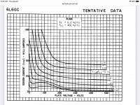
Thank you! I'm really surprised with the high screen currents, based on those curves, yes, they can be quite high. But the average current is still relatively low, and the power dissipation, as far as I understand (I may be wrong!), is about the average current. The MOSFET, of course, needs to be able to handle short high current peaks, but the one I'm planning to use can handle 1.5A continuous at 100deg, and 9A peaks, so it should be OK.
My first try will be without voltage regulator anyway, I will try several options, like UL taps, or unregulated voltage, and will take it from there.
My first try will be without voltage regulator anyway, I will try several options, like UL taps, or unregulated voltage, and will take it from there.
- Home
- Amplifiers
- Tubes / Valves
- Chassis or dedicated heatsink for MOSFET