I opted not to use the third input. After previous advice from DF96 I then tied all of the unused inputs on v1 to ground.
Just be careful not to confuse my advice about grounding unused valve electrodes and kward's advice about grounding inputs as a debugging tool. Both are valid, but are different things for different purposes.
I grounded pin 1 of the 6sl7 and injected a signal at pin 4 of the 6sl7. I get the signal I put in and almost inaudible hum. When I pull the first 6sl7 I still have the hum, when I pull both 6sl7's I get no hum, but when I do that and inject a signal at pin 4 I get practically no audio, it is only slightly louder when injected at pin five of the 6l6. This hum is odd, it sounds like amplifiers that I have worked on with broken ground, low to no signal audio and deafening hum. I have checked all my grounds and signals, and they are good. I may just completely scrap the front end and rebuild.
As I don't carry 6SL7 pin numbers around in my head, could you put that in terms of electrode names?I grounded pin 1 of the 6sl7 and injected a signal at pin 4 of the 6sl7.
If you inject signal into a valve socket with no valve you won't get much sound out. You need to be clearer when you describe to us exactly what you did, and what you found. Remote debugging is not easy!
Ok I don't get it, you say when you pull both 6sl7's, you get no hum, but when I do that? (pull both tubes?) and inject signal to 4 (how you just pulled them?).
Question:
1- With just the powertubes in, no hum - right?
2- with powertubes in, and driver tubes in ( second 6sl7), hum or no hum?
3- with all tubes in and pins 1 & 4 on first 6sl7 grounded, hum or no hum?
Something silly! you used one 6sl7 for all the inputs, and another for driver section, right?
You did not use half of first tube for one input and other half for driver, did you?
Last edited:
Sorry about that DF. I grounded the first grid of the second 6sl7 and injected a signal into the second grid of the second 6sl7.
You should get signal out, although of course not as much as if the first stage was in operation but much more than when you inject the same signal to the output stage grid.stridor said:I grounded the first grid of the second 6sl7 and injected a signal into the second grid of the second 6sl7.
If the Cathode is grounded (ie. attached right to ground with no resistor in between) and you then ground the grid--best not be anything attached to the anode with a voltage on it.
Just list the pins on the input tube and what is attached to them as far as resistors and voltages.
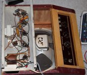
Here is a picture of a little Gretsch amp I have. It has the filament circuit grounded on one side and everything else is grounded all over the chassis and it's pretty darn quite. And I even put a three prong plug in it with ground to the chassis. So something is wired wrong.
Just list the pins on the input tube and what is attached to them as far as resistors and voltages.
Here is a picture of a little Gretsch amp I have. It has the filament circuit grounded on one side and everything else is grounded all over the chassis and it's pretty darn quite. And I even put a three prong plug in it with ground to the chassis. So something is wired wrong.
Attachments
I just took some alligator leads and connected the earth grounded chassis, the ground bus, and the signal grounds, and the hum went away and everything works as it should. I think I'll just keep doing it that way.
That suggests that something was not connected before.
I don't understand your distinction between 'ground bus' and 'signal grounds'. Aren't these the same thing?
I don't understand your distinction between 'ground bus' and 'signal grounds'. Aren't these the same thing?
NoThat suggests that something was not connected before.
I don't understand your distinction between 'ground bus' and 'signal grounds'. Aren't these the same thing?
he had said before he had lifted his signal ground from chassis.
Remember the 2W resistor discussion, and live leak into signal earth?
I did ask him, as to why he had done that in the same post.
I am glad he got to the bottom of it at the end.
To be honest, I am so swimmy headed from that crazy schematic, and Neutral, vs earth, vs dc ground, vs chassis ground that I couldn't tell you. What I can tell you is this; if it isn't live AC, signal, or B+ it is presently connected to the steel chassis.
I realise that chassis and signal ground are not the same.
What is 'signal ground' if it is somehow different from 'ground bus'? Which ground has the bus, signal or safety? I suspect that he had omitted a connection between two things which were both supposed to be ground.
What is 'signal ground' if it is somehow different from 'ground bus'? Which ground has the bus, signal or safety? I suspect that he had omitted a connection between two things which were both supposed to be ground.
My bus wire had HV center tap, filter cap negative and any part of the circuit that was negative with respect to b plus. The chassis was third prong earthed. The metal backs and the sleeve of the input jacks were tied together and hooked to the bus as well. I found 120 ac on the sleeve of my output jack so I connected everything to the steel chassis. Hv center tap, cathodes, sleeves, filter cap negative, and. The body of my pots. No more deafening hum, works as expected.
OK, you must have omitted a ground connection somewhere. Now it is all grounded, although perhaps not optimally. Connecting everything to the chassis puts you back to 1950s grounding practices, so you will get 1950s hum.
Undoubtedly so DF. I don't know, what I missed. I really had high hopes for this build and wanted to make it quiet; but the truth is I'm a solder slinger. As much as I would like to, I don't build beautiful instruments to soothe man and beast. I build monstrosities of iron to bludgeon the masses with.
Last edited:
..................
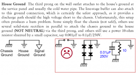
If you got ground loop problems, at least connect a 10R/2W between your signal ground and chassis - for safety.
......................
A 2W resistor won't last very long if there is a short. It may give the illusion of safety until something nasty happens. You need something which can survive a fault current longer than the mains fuse or breaker.
The Fault Current can approach kilo-Amps.Ok use a 10W - my home circuit trips instantly, but I suppose in older systems with a wire fuse, you would be correct.
A small Fault Current of 40Apk would try to dissipate ~16kWpk in your resistor.
The 10r resistor would also try to protect the mains fuse for long enough such that you have time to get off your butt and go and touch the now "apparently non operational" equipment and get a potentially fatal shock.
DO NOT insert a resistor into the Main Audio Ground to Protected Chassis route.
Wow! KILO Amps? through a small amplifier, into a guitar pickup?The Fault Current can approach kilo-Amps.
A small Fault Current of 40Apk would try to dissipate ~16kWpk in your resistor.
The 10r resistor would also try to protect the mains fuse for long enough such that you have time to get off your butt and go and touch the now "apparently non operational" equipment and get a potentially fatal shock.
DO NOT insert a resistor into the Main Audio Ground to Protected Chassis route.
his butt would be on fire, playing AC/DC for real!
Well I never . . .
What are the chances of ACCIDENTALLY a live wire being bolted into a signal ground?
The only thing that could have happened, would have been a spark or some component shorting (such as a capacitor) to leak HV into a ground wire.
The 10R is enough to deal with such unlikely events, and to trip the fuse (HV fuse).
Also it is large enough not to cause much ground loop.
It is a usual practice, just google it.
I would have that you would always want chassis ground and house ground to be firmly linked, not lifted as in the Dot manual examples. The discussion, surely, should be about lifting signal ground from chassis/house ground, not lifting chassis ground from house ground?
Chris
Chris
- Status
- Not open for further replies.
- Home
- Amplifiers
- Tubes / Valves
- chassis grounding questions