I am sorry for laughing! 🙂 😱 🙂 but we all have done that - I have done worse!Well, I got done with this build, and I must say that I am thoroughly dissatisfied. It's like I connected a dc power supply, and a poorly filtered one at that, to a speaker.
you'll find out where you've gone wrong - I have faith (in you, not generally)
No. A bus is a length of wire. A star is a single point.KenTajalli said:An earth bus, if kept short, is also a star!
That is a ground loop, albeit a small one. Generally, it is best if the 'star' ground is not actually at the chassis but separate - but then with a single connection to the chassis.get a thick single core wire shape it like a two inch staple, and connect both ends to your chassis.
A heater supply must have a DC reference voltage, which in many cases may be ground. Nothing inside a valve envelope should be left floating.Frankly I would not earth one side of the heater supply.
An old-fashioned 'ground to local chassis' arrangement is good enough for radio receivers and guitar amps. You get some hum, but not too much. It has the advantage that you don't have to think about grounding. Doing it properly is harder, and easier to get wrong, but when you get it right the hum just disappears.stridor said:Well, I got done with this build, and I must say that I am thoroughly dissatisfied. When I was ignorant and connected each and every single ground to the most convenient place I could put a dollop of solder on the steel chassis I got better results than this meticulously planned pile of crap I have built. The hum is so bad there isn't any audio.
This is a guitar amp I am building. I am ok with some hum, but this is ridiculous. You mentioned that nothing inside the tube should be floating. So should I ground all unused pins on all of my tubes? Also, my ground is essentially floating since it is connected to the HV center tap. Should I connect it to the chassis along with earth ground? Also, once again, thanks to everyone who has helped me with this, it's gonna make me a better amp builder some day. Right now I'm just a solder slinger.
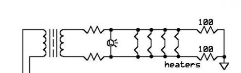
I have no idea what the culprit is really. I have put a scope on the input and output of the first 6sl7 going into the PI and it is total garbage from the get go, so that is only going to be amplified as it moves through the amp. When I say garbage I don't mean a 60hz signal riding in, I mean I get a green wash across the entire screen of my scope. Its big, it's ugly, and it is happening in the first tube. But I will try the circuit you posted Ken. The first two resistors, are they 100 ohm?
you only need the last two. anything from 47R to 150R - make them 1W.
Did you try my acid test?
Just momentarily disconnect heater supply and see if the noise goes away - tube should remain hot enough for a few seconds.
Did you try my acid test?
Just momentarily disconnect heater supply and see if the noise goes away - tube should remain hot enough for a few seconds.
Also I am not up on guitar amps.
You seem to have three inputs, could noise be leaking from them?
Check your B+ with your scope, see how clean it is, while the amp is running.
Earth your scope properly to the amp using a separate wire.
You seem to have three inputs, could noise be leaking from them?
Check your B+ with your scope, see how clean it is, while the amp is running.
Earth your scope properly to the amp using a separate wire.
You may also just want to take a step back and examine what you've got. If you've built to the topology shown in your opening post (because of capacitor coupling between stages), you should be able to determine which stage is introducing the hum fairly easily.
Before you start, check a couple of things:
1) Make sure the coupling caps are not leaky. Leaky caps can introduce hum and also play havoc with tube biasing.
2) Make sure your power supply is delivering relatively quiet DC. If you've got a wiring error there, or a leaky filter cap, the noisy B+ supply can cause hum.
3) Make sure your filament circuit has a ground reference. Use an alligator clip lead for now if you need. Connect one side of the filament secondary straight to circuit ground (for now--not a permanent solution), it will get you past this as a potential hum problem for now so you can see the next hum problem behind it.
4) All grids of all tubes need a DC ground reference. If the grid of your gain stage tube does not have a ground reference, it will cause massive hum similar to what you described as seeing "white wash" on your scope. Again for now, just use alligator clip lead if needed, connecting straight from pin 1 to circuit ground.
Now you're ready to do some debugging:
1) Remove all tubes except the power tubes. Fire it up and see what you've got. If it's quiet move to the next stage.
2) Add the phase inverter tube and fire it up. If it's noisy, it's something in this stage that's introducing it.
3) Add the first gain stage tube and fire it up. If it's noisy, it's something in this stage that's introducing it.
There are diverse ways hum can be introduced. I'm sure you can make this amp quiet if you start eliminating causes of hum one by one.
Mods might want to move this thread to the right forum.stridor said:This is a guitar amp I am building.
If the pin has nothing inside connected to it then it should be left unconnected outside. All other unused pins should connect to something outside, typically either ground or a cathode.You mentioned that nothing inside the tube should be floating. So should I ground all unused pins on all of my tubes?
The audio ground should connect to the chassis somewhere. At the input socket is often a good place.Also, my ground is essentially floating since it is connected to the HV center tap. Should I connect it to the chassis along with earth ground?
Parasitic oscillation?When I say garbage I don't mean a 60hz signal riding in, I mean I get a green wash across the entire screen of my scope. Its big, it's ugly, and it is happening in the first tube.
All of my components are new, so they should be ok, not saying a new part can't be bad, just not as likely. My dc supply is fairly quiet according to the scope, I have ~ 15 mv of ripple. Honestly, the method I am using for grounding is so foreign to me and has me so stymied that I am not sure anything is grounded. I am not sure that I am understand what you mean by grounding the grids. That is where the signal goes in so wouldn't it just send all the signal to ground? Also, it would seem like grounding pin one of the first 6sl7 would also send all the signal to ground.
Correct, it's all temporary to isolate where or how the hum is being introduced. It's a way to gather evidence and clues. Example: if alligator clipping pin 1 of the first gain stage to circuit ground makes it quiet, and then removing the alligator clip reintroduces the hum, then look at the 1 Meg grid leak resistor on pin 1. Is it an open circuit? Is there a wiring error? Is there a bad solder joint? Is there noise being introduced somewhere along the input wire from the RCA jack to where it connects to the grid pin? Etc.
Ah, Ok, thanks for clearing that up. I promise that I actually have a clue what I am doing. I am going to try all these suggestions and when I get it fixed I'll post my results so you guys can see what you helped me make.
An externally hosted image should be here but it was not working when we last tested it.
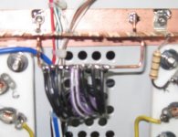
this is how I set my buss up. I stripped the insulation off of a length of 12 gauge copper wire and left the insulation on the ends which formed into loops and secured it with nuts and bolts. The hv center tap, and all other circuit grounds go here I earth grounded the chassis to the third prong.
Last edited:
well your picture is not showing, but no matter.An externally hosted image should be here but it was not working when we last tested it.this is how I set my buss up. I stripped the insulation off of a length of 12 gauge copper wire and left the insulation on the ends which formed into loops and secured it with nuts and bolts. The hv center tap, and all other circuit grounds go here I earth grounded the chassis to the third prong.
If I read your explanation correctly you hooked up your chassis to your mains supply earth, but kept your signal ground away from it, right?
That should be OK, so you lifted your ground, why? do you get more hum otherwise?
Also from a safety point of view, since this is a guitar amp, have you considered what happens if you get a live short to your signal ground? yep, it will travel to your pickups and YOU!
If you got ground loop problems, at least connect a 10R/2W between your signal ground and chassis - for safety.
Yes, that neatly combines a ground bus and a ground loop all in one simple piece of wire.KenTajalli said:My idea of star (err sorry BUS) ground.
A 2W resistor won't last very long if there is a short. It may give the illusion of safety until something nasty happens. You need something which can survive a fault current longer than the mains fuse or breaker.If you got ground loop problems, at least connect a 10R/2W between your signal ground and chassis - for safety.
Ok use a 10W - my home circuit trips instantly, but I suppose in older systems with a wire fuse, you would be correct.A 2W resistor won't last very long if there is a short. It may give the illusion of safety until something nasty happens. You need something which can survive a fault current longer than the mains fuse or breaker.
So are you using about a 15 meg. resistor for R22 (to pin 4 or pin 1 of the 6SL7)? And C16 is not grounded right? That is a third input. Just checking...........
What is that input for?So are you using about a 15 meg. resistor for R22 (to pin 4 or pin 1 of the 6SL7)? And C16 is not grounded right? That is a third input. Just checking...........
I mean the entire section ( R22, C16 and the triode)
- Status
- Not open for further replies.
- Home
- Amplifiers
- Tubes / Valves
- chassis grounding questions