Hello!
I like to now if i can Change in my Preamplifier the value of the coupling capacitor from 0,47uf to 0,56uf ?
Best regards!
I like to now if i can Change in my Preamplifier the value of the coupling capacitor from 0,47uf to 0,56uf ?
Best regards!
Last edited by a moderator:
Schematic, please! Decent advice is not possible, without a schematic.
I don't need no schematic. 0.47 or 0.56 is a trivial difference.
Jan
Perhaps he is upgrading the caps to better sounding types.
Agree with Jan: such a difference for a coupling cap is trivial and increasing the value will only imperceptibly extend the low frequency range.
Agree with Jan: such a difference for a coupling cap is trivial and increasing the value will only imperceptibly extend the low frequency range.
Undoubtedly, such a small change will have little, if any, impact. However, a schematic allows us to make sensible recommendations, including doing nothing.
My point is that you can make sensible recommendations without a schematic too. You just did Eli 😎
Jan
Jan
There is little point in changing from 0.47µF to 0.56µF. Why do you want to do it?
Emphasis added.
Why? … because change itself is very often the driving goal of DIY audio folk. Change to see what effect there is (tho' that begs, “then why ask us first?”) if any. Then there is change to dog perfection, whatever perfection is defined to be. Silver foil separated by hemp oil soaked virgin bamboo fiber paper…
Another poster suggested (loosely quoting) “substituting 0.56 µF for the present 0.47 µF would almost imperceptibly extend the low-frequency response a bit, at most”.
Even that is likely an overstatement! If the preamp was “correctly designed” at the outset, the 0.47 µF coupling capacitor's low-cut knee is well below 20 Hz to begin with. Very probably around 5 Hz to 7 Hz. So … dropping that knee 100% × (1 - (0.47 ÷ 0.56)) = 16% of 5 to 10 Hz leading to 4.2 to 8.4 Hz … is deep in the inaudible subsonic range.
Lastly, working mathematically backward … if the 'test' is just to see what a change-of-value does, as opposed to replacing the cap entirely, then
CTOT = C₁ + C₂
0.56 µF = 0.47 µF + C₂
0.10 µF ≈ C₂
So, all that is needed is to tack-solder a little high quality 0.10 µF cap to the existing one. Again… why ask us first?0.56 µF = 0.47 µF + C₂
0.10 µF ≈ C₂
Best of luck.
“just do it”, then see.
GoatGuy ✓

No point in changing output cap here. The only difference is that the board may get damages.
Use the money to buy music instead !
Use the money to buy music instead !
Since nobody knows the input impedance of the following amplifier, nobody can predict what it will happen.
Probably nothing . . .
Yves.
Probably nothing . . .
Yves.
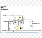
Good point. Looking at the actual valve used the following stage better have a high input impedance. Standard 10k transistor amps won't work well at all.
Going by that partial schematic, it appears that changing that .47u cap would not change performance unless the following stage has a very, very low impedence. And even then, the difference would not be audible.
With high impedence tube circuits, I don't understand the reasoning for using such high capacitance values for coupling. It effects response speed in some cases by loading down signal/level changes, and having an amplifier with ability down to sub-sonic levels is deterimental to performance as well. Who really needs to listen/have soundwaves at 10 hz in their music anyway? It only causes woofer "flopping" and increases rumble and hum effects. And that makes what you hear as music sound crappy.
I don't like crappy sound, but that's just me I guess.
What sort of load are you trying to drive with that parallel section setup, "kompakt"?
While the 12AU7/ECC82 exhibits a reasonably low plate resistance (RP), the 10 Kohm IHF "standard" load will be problematic.
While the 12AU7/ECC82 exhibits a reasonably low plate resistance (RP), the 10 Kohm IHF "standard" load will be problematic.
Last edited:
If the design calls for 0.47uF, but all you have in stock is 0.56uF then it is fine to use them. In most cases 0.33uF or 0.68uF would be OK too.
Hello!
thank you for your answer. the only reason to change is that I have a pair
of Mundorf Silver Oil 0,56 for test here!
Maybe i let it better by 0,47uf!
Best regards!
thank you for your answer. the only reason to change is that I have a pair
of Mundorf Silver Oil 0,56 for test here!
Maybe i let it better by 0,47uf!
Best regards!
Image in post #3 fixed. The reason it froze the thread and wouldn't open is because the link ran to tens of thousands of characters in length.
Please try and attach images using the forums own option. Then they are here for keeps:
How to attach images to your posts.
Please try and attach images using the forums own option. Then they are here for keeps:
How to attach images to your posts.
Since nobody knows the input impedance of the following amplifier, nobody can predict what it will happen.
Probably nothing . . .
Yves.
Yes we can. Whatever the load is, the cut-off frequency will change by about 20% (lower with the 0.56). Trivial.
Jan
- Status
- Not open for further replies.
- Home
- Amplifiers
- Tubes / Valves
- changing the value of coupling capacitor