Alot of cheaper CDPs use the DAC supply rails to power IV op amps (ie. Sony) and the de-emphasis filter, all usually done with 2 x dual 8 pin dip op amps. Its typically +/- 5V DC at the op amps.
In that circuit I don't see any PS decoupling on the 2100s, which is critical on any higher speed op amp you'd upgrade with, otherwise you risk oscillation or other instability.
The muting circuit should also be bypassed (remove the 2 transistors close to the output jacks), but be aware there may be strange noises during track search or power on/off. Usually nothing serious, but I'd be careful powering it on after the amp is running.
Your CDP looks like a JVC unit in drag. The DAC isn't anything to write home about - sorry. Maybe a pair of NE5532ANs would be a decent upgrade, but only with decoupling the PS rails with ceramic 100nf caps at pins 4/8. A small series resistor (47 - 100 ohms) in line, forming an RC at pins 4/8 can help with noise getting into the op amp. In this case, use 10uf parallel with 100nF ceramic on each supply pin of each op amp.
Some Nichicon Muse ES bipolar caps at coupling locations would make a good difference depending on how good the original caps are.
If you're looking for a cheap used player that would be a step up in SQ, any older Philips (TDA1540/1541/1543) based CDP would leave it in the dust it in terms of SQ. Sometimes its easier and.cheaper to start with a better player, then mod it. All of the Sony CDP 5xx, 6xx, 7xx with multi bit converters (ca. 1986 - 1992) have excellent potential for a budget player with mod potential. The laser unit on these is unfortunately not the most long lived and won't read computer generated CDRs very well. The older single beam swing arm pickup Philips players read just about anything and last a long time. Caps are the main thing which go bad in those.
Last edited:

Wouldn't the NE5532 (my favorite do it all opamp) need a little more voltage?
The what I think to be the coupling caps are lowest quality, like all parts.
With such modifications a very important factor is the one who does them. Things that are simple basics for one may be over the top for another person.
Using another opamp could even increase the output level a bit. Adding a simple, cheap dual voltage, LM317/337 module could make things even better.
Anyway, at some point selling this one unmodified, only cleaned and buying another, used CD player, may be more attractive.
@Turbowatch2 As long as the load isn't too hard, any of the NE5532 are just fine with +/- 5 VDC. The 22 pf cap in the NFB loop is important for unity or low gain circuits, as is some small ceramics on pins 4 and 8 to ground.
I agree that some separate +/-15 V regs on the op amp supply rails is a good idea. The problem is that it requires a separate transformer with at least +/- 15 VAC (before rectification) to feed it. The cheaper model CDPs share the DAC supply rails with the IV stage op amps.
I agree that some separate +/-15 V regs on the op amp supply rails is a good idea. The problem is that it requires a separate transformer with at least +/- 15 VAC (before rectification) to feed it. The cheaper model CDPs share the DAC supply rails with the IV stage op amps.
Last edited:
I go with the capacitor / resistor swap first. But I will look all the tips you all give me.
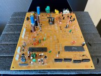
I first tought there was one op-amp pr canal. But L / R signal comes from same op-amp and then go to RCA. A 4.7uF cap and 220 ohm resistor in series with signal. And 3800pF couplingscap.
Here are the partlist.
I first tought there was one op-amp pr canal. But L / R signal comes from same op-amp and then go to RCA. A 4.7uF cap and 220 ohm resistor in series with signal. And 3800pF couplingscap.
Here are the partlist.
Attachments

As we don't have a shematic for this player, most are some ideas that could work, but not percise instructions. If one had the object on the table, there could be other options, depending on voltage measurements for example.
If you are right about a single opamp driving the output, what is the second one for? Just seen from the pictures, there are two identical set's of parts around the two opamps. Also both opamps have an identical pencil mark. So maybe check again?
If you are right about a single opamp driving the output, what is the second one for? Just seen from the pictures, there are two identical set's of parts around the two opamps. Also both opamps have an identical pencil mark. So maybe check again?
Turbowatch2: The path goes from pin 7 ( output ) on Op Amp ( IC701) ) to pin 5 ( + input ) on Op Amp ( IC702 ) then out on pin 7 to RCA right canal.
The adder goes from pin 1 ( output ) on Op Amp ( IC701 ) to pin 3 ( + input ) on Op Amp ( IC702 ) then out on pin 1 to RCA left canal.
So they then are in series I think. The pin 5 + input on ( IC701 ) come from IC200 ( HD404729S ).
The pin 3 + input on ( IC701 ) comes from IC700 ( 5876 ).
The adder goes from pin 1 ( output ) on Op Amp ( IC701 ) to pin 3 ( + input ) on Op Amp ( IC702 ) then out on pin 1 to RCA left canal.
So they then are in series I think. The pin 5 + input on ( IC701 ) come from IC200 ( HD404729S ).
The pin 3 + input on ( IC701 ) comes from IC700 ( 5876 ).
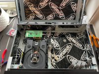
Hi again, now the parts are in place. The board is back in the player. I power it up and put in a cd, the drawer goes in.
The cd starts to spin ( clockwise seen from the label side of cd, not readingside ), it spinns for 2-3 sec. And at the same time the laser trying to go to center of cd, hitting the end stop ( I can see it move into center and it make a rattling noise, think maybe the tiny plastic driving wheels also jumping some teeth ). But I see the mecanism of the tooth rack driven by the driving wheel has a spring effect, so I think it is a security if motor just pushing on it skip insted of damage anything. So after the 2-3 sec it stops and start spinning backwards for a 2-4 sec then stop. The laser look maybe week but I can be wrong. I have also 5 times check the pcb for right value, direction of electrolytics and solder joints. Damn, now I have done it 😱
The cd starts to spin ( clockwise seen from the label side of cd, not readingside ), it spinns for 2-3 sec. And at the same time the laser trying to go to center of cd, hitting the end stop ( I can see it move into center and it make a rattling noise, think maybe the tiny plastic driving wheels also jumping some teeth ). But I see the mecanism of the tooth rack driven by the driving wheel has a spring effect, so I think it is a security if motor just pushing on it skip insted of damage anything. So after the 2-3 sec it stops and start spinning backwards for a 2-4 sec then stop. The laser look maybe week but I can be wrong. I have also 5 times check the pcb for right value, direction of electrolytics and solder joints. Damn, now I have done it 😱
Attachments
Hmmm... so you have gone from a working player to a zonked one following the recap 🙁
You need to recheck all your work and look for things like tiny solder splashes that might be shorting traces or leads. I'm afraid we do see this a lot following recaps and the like. No easy answer I'm afraid and without circuit diagrams it all becomes a whole lot more difficult. Recheck everything for a start.
You need to recheck all your work and look for things like tiny solder splashes that might be shorting traces or leads. I'm afraid we do see this a lot following recaps and the like. No easy answer I'm afraid and without circuit diagrams it all becomes a whole lot more difficult. Recheck everything for a start.
I usually can see right off the bat whether a player has potential for improvements. I've modified alot of CDPs and have learned some valuable lessons, some not so cheap. The thing you need to be aware of is the level of performance the player is capable of with minimal component substitutions. There isn't much point if the power supply isn't capable of delivering noise free power, especially when the grounding scheme isn't good to begin with. The better players have separate voltage rails for analog and digital sections. If thats not the case, it won't pay off to start swaping regulators and filter caps. Theres also the issue of the DAC itself, whether it has the potential for delivering better low level resolution and the output filter itself. Jitter is a massive issue with older units. Thats usually down to the way the clock is set up and how its distributed through the chain of components.
Then there's the issue of the laser itself and the predicted remaining life span. The spindle motor is also a wear item and suffers from brush and bushing wear. The player here looks like it has a HOP-M3 pickup, which is an excellent type. Alot of these older Japanese players use Sony or Philips transports, of which the Sony models aren't that reliable.
Hopefully the problem with the transport is just a limit switch alignment issue. It doesn't take much to screw up a P/U unit through lightly mishandling it.
- Home
- Design & Build
- Parts
- Change Op-Amp / Caps in CD player