For now I've decided to go for something simple to start out. I don't care how good or bad chip used will sound in the end, I just want to get my feet wet and have a finished product that WORKS :\
Among the many SMD chips I have, which will be too small for me to work with at this point in time, I have a bunch of through hole chips I'd like to maybe have a go at.
With that said, I now am wondering a couple things. The first Q(s) is a sort of "What is this and will it work?" I've got a few chips that my Google searching and Datasheet site browsing have turned up zilch for, but some have turned up possible hits (different part number prefix which I'm not sure if it changes the part function entirely or not).
As I have a new motherboard with a far superior audio codec than my last one, I've put aside my desire for a headphone amp. I'm now looking to drive 2 to 4 Logitech Z-560 Tang-Band (15W I believe, and I can dig up the Ohms if needed) Sat speakers. Mainly for simple Windows audio.
First is a Sanyo disconn item: STK5446 (I cannot find a datasheet or other info except These two things.)
-On the bottom right corner, in smaller font reads 1D09. On the thermal side is stamped 5446B and under it CC94 (Date code I assume given the age of the unit it came from)
Next: LA6510
-Has 4R9 on the line below. Not sure if that 1A output current is considered good or not... As the datasheet image show, it has a small metal, what I'll call "mono-fin heatsink" stick out the top with a hole. So if it is a decent choice I can probably sink it if that'll help any lol
Finally, which I think might be the best option: BA10324A (Here is also an older scanned original)
-There are a few other listings for datasheets on it, one being very long except it has an added F suffix (although... this one DOES list it in with the A and another), which could mean a whole lot as I've discovered so is pretty much irrelevant I think. It has no discernable manufacturer screened on it (to my untrained eye at least).
Honorable Mention, since I have 4 or 5 of them, and I'll who it verbatim how it reads off the chip...
2903D
---JRC
-.4047G
I've only bee able to track down a datasheet using "JRC2903D" but those results are a mixed bag it seems. It seems like possibly "NJR2903D" is it's new part number as NJR and JRC are one in the same or have merged. I thought I had a datasheet for it, but I can't seem to find it anymore 🙁 I THINK it was called a "Op Amp Comparator", which I've not exactly dug into what it's function is short of what it's name implies 😕
So yea, essentially wondering which would be the best one to start with. As for powering it, I could REALLY use suggestions. My plan is to spend almost nothing and use all the random parts I've salvage around here (which is amassing to be quite the assortment), with hopefully the only thing I'll need is resistors. Some of them I noticed the voltage requirements being a tad up there, I assume that ones showing -/+15V are essentially 30V components. While I have transformers around that I believe can supply, one that came out of the same component of the STK5446 was showing in the 40V area, but I have zero knowledge on how to wire up a transformer (the PCB it was on broke when I dropped the beast... oops) 😱 And this might be a tall order, but from what I can tell some/all of those don't have a simple working circuit diagram, so if anyone would have an idea of how to wire one up for audio (provided they can do that), that would be a HHHHHHUGE help!!
Thanks again for everything!
-Clint
Hi there,
as you've somewhat reduced your desired specification level, you might like to have a look at this Ebay item;
TWO, new 80W rms HI-FI Amplifier ICs type LM12 LM12CLK on eBay (end time 09-Oct-10 19:31:13 BST)
Only two of them, I'm afraid as I might have had a bid for them myself.
Seriously high powered simple Op Amps with 10Amp output capability. Internal protection and no messing about with bootstrapping and all the other external components that most of the "Hi Fi" chips seem to require.
Theoretically, 1 one LM12CLK plus half a dozen external components will give you a 60W amp into 8R.
Sandy
Hi there,
as you've somewhat reduced your desired specification level, you might like to have a look at this Ebay item;
TWO, new 80W rms HI-FI Amplifier ICs type LM12 LM12CLK on eBay (end time 09-Oct-10 19:31:13 BST)
Only two of them, I'm afraid as I might have had a bid for them myself.
Seriously high powered simple Op Amps with 10Amp output capability. Internal protection and no messing about with bootstrapping and all the other external components that most of the "Hi Fi" chips seem to require.
Theoretically, 1 one LM12CLK plus half a dozen external components will give you a 60W amp into 8R.
Sandy
While they are pretty cheap, you'll have to just nab them all 🙂
As it only "Ships to:United Kingdom", and I'm in the States :\
Appreciate it though!
First is a Sanyo disconn item: STK5446 (I cannot find a datasheet
Then don't touch this IC.
LA6510
The TDA7560 you already have is easier to build. It only takes one input capacitor per channel and two resistors and two caps for muting and standby and four caps for the power supply. You should try to finish that before starting anything more complicated.
BA10324A
That is an op amp. It will not give sufficient output power to drive any serious speaker load other than headphones.
It seems you are trying to take the second step (building) before the first (understanding).
While they are pretty cheap, you'll have to just nab them all 🙂
As it only "Ships to:United Kingdom", and I'm in the States :\
Appreciate it though!
However, if you search Ebay your side of the pond for LM12 you'll find quite a few over there, as well.
Sandy
If you have a power supply and a fair set of resistors and capacitors, why not just request a few samples of some audio IC's? For really simple you could go with something like an LM1875 or LM3875. One channel per IC seems simpler to me than 4 channels per IC. It's a lot easier to solder at least 🙂
Then don't touch this IC.
[/quote
I guess what I implied was: "Does anyone know what this is and/or have the datasheet" :\ It's alright though 🙂
The TDA7560 you already have is easier to build. It only takes one input capacitor per channel and two resistors and two caps for muting and standby and four caps for the power supply. You should try to finish that before starting anything more complicated.
I know, but the problem is my breadboard's holes are spread out just a tad too much and I really can only fit in 2 channels. Which is fine, but it got a bit frustrating when I went through all the work of getting it all laid out how it "should be" and then I find that the datasheet I'm looking at is for the non-A. To make matters more confusing, the A datasheet doesn't mention an off-set pin package (horizontal I believe it was calling it), only the other SIP (vertical) package. So I had to take everything out that I just got done laying out, bend a whole bunch of other pins around (snapping one of the "TAP" pins, which I have no clue what is) then try my best to go through the pins, count which one should be what, and then hope I did it all correctly :\
If this 6510 will work though, I'd much rather use it, as its pins all line up perfectly with my breadboard.
That is an op amp. It will not give sufficient output power to drive any serious speaker load other than headphones.
It seems you are trying to take the second step (building) before the first (understanding).
Well I originally had planned on a HP build, but my new motherboard has wwway more than enough power now.
I won't argue with you there. I don't pretent to understand what I'm doing, and I mentioned that in my "New Members" welcome area, as well as the other thread about the 7560. I have learned quite a lot (IMO at least) in the last couple weeks, going from little or no knowledge, to... well substantially more but still far short of what would be useful 🙁 That's why I want to try and build something first, because I'm a hands on person. So if I can manage to get just one done first, no matter how good or bad it sounds, it'll make things easier for me.
However, if you search Ebay your side of the pond for LM12 you'll find quite a few over there, as well.
Sandy
I know, I had. They're about 20x what I'd want to spend heh And that is just for ONE part!
As I said before, I just want to toss something together to get things rolling. I've already screwed up one circuit (TDA2822M) two or three times, I just don't want to risk killing anything yet that I've paid for or is of good quality.
If you have a power supply and a fair set of resistors and capacitors, why not just request a few samples of some audio IC's? For really simple you could go with something like an LM1875 or LM3875. One channel per IC seems simpler to me than 4 channels per IC. It's a lot easier to solder at least 🙂
They may not be an ideal means of power, or recommended for that matter, but I have ways of supplying power. I also have a boat load of capacitors ranging from small to large in capacitance and voltage, and good quality to average quality and even shoddy quality that I wouldn't even consider using in an audio build heh
And I've thought about asking for samples before, but I've never really knew what to put down in the request form. They always ask for a company and I can't imagine they'd send them out if I was to put "personal use" or something, or if I lie and make up a company what would I even put 😱
What kind of power supplies do you have? Single or split (aka dual, +/-), what voltages?
A transformer on the order of 30V - 50V AC would be good if it has a centre-tap (so you have 15V - 25V AC from the centre-tap to each secondary), or if it's dual secondaries, 15V - 25V AC for each secondary.
What impedance are the speakers you want to work with?
The speakers you mentioned above, being 15W, sounds like an LM1875 would be a good starter project. It's capable of about 20W, and only 5 pins.
Last edited:
What kind of power supplies do you have? Single or split (aka dual, +/-), what voltages?
A transformer on the order of 30V - 50V AC would be good if it has a centre-tap (so you have 15V - 25V AC from the centre-tap to each secondary), or if it's dual secondaries, 15V - 25V AC for each secondary.
😕😱 Lots of DC stuff is about it. Save for computer SMPS which has -12v (but only .8A on that rail), it's just +/- stuff. Sadly all I have are rectifiers ICs too, no inverters.
I have transformers, but they are all of the PCB flavor, not that I know how to wire them anyways 🙁
What impedance are the speakers you want to work with?
The speakers you mentioned above, being 15W, sounds like an LM1875 would be a good starter project. It's capable of about 20W, and only 5 pins.[/QUOTE]
8Ω

I'm starting to get the feeling I should stick to computers and cars

Ironically I decided to see exactly HOW powerful this onboard audio is, and at 89% volume, it is very capable of driving 2 of the above speakers. Though I suspect given it is likely intended on driving passive speakers of a much higher Ω, that prolonged usage will result in the burning out of something so... it was just a test in the end heh
Try something even less stressful for a first project, try a ready-assembled kit. Radioshack or similar consumer electronics stores should have some kind of 5-20W amp kits with circuit board and all components (except transformer and heatsink). There's some REALLY cheap LM3886 and Tripath amp kits from China on eBay but I don't trust those as they're 1/2 the cost they should be for the components included.
Last edited:
I'm starting to get the feeling I should stick to computers and cars
It's not that bad, but you can't just pick up a bunch of stuff from your bench and assemble an amp without doing some research and making some decisions.
Given that those are 8 ohm speakers, the LM1875 would do nicely. If you don't feel like asking for samples (I still recommend that), they are only about $5 each (you would need one per speaker).
A PC power supply would work okay for low to moderate listening until you could afford to put together a better one. 0.8A is a bit low, but as long as you don't push it, it should be okay. Do you know how to make a PC power supply run outside a computer?
Try something even less stressful for a first project, try a ready-assembled kit. Radioshack or similar consumer electronics stores should have some kind of 5-20W amp kits with circuit board and all components (except transformer and heatsink). There's some REALLY cheap LM3886 and Tripath amp kits from China on eBay but I don't trust those as they're 1/2 the cost they should be for the components included.
As logical as that is, I would actually prefer to go about getting it all together myself with out having to resort of a kit :\ On that note, as I've already just about gone through all three of the 30x24 breadboards I got (which are crappy quality anyhow), I've been toying with the idea of something like this big guy. A friend owes me money and has been less than prompt on the payback, so I've been trying to give him small things he can repay me with. If he still won't, there is a smaller one for $5 w/o power posts as well. That way it wouldn't result in as much frustration since I could just pop stuff out of the board and move them if... well when, I screw up. So while I really have no budget to play with, which is another reason for not wanting to buy anything, that would at least be reusable and useful on unrelated projects.
It's not that bad, but you can't just pick up a bunch of stuff from your bench and assemble an amp without doing some research and making some decisions.
Well I don't necessarily think I can just pick up anything I have laying around and make an amp out of it lol Everything I've asked about I've researched and found as much as I could about. Like in the case of the first item which I couldn't find a datasheet, I only mentioned it thinking possibly someone may have an idea of what it is. It's a 10pin SIP and was in the power supply section of the component I pulled apart, so my assumption was either a buck/boost converter, amplifier, or rectifier of sorts or a VR.
Given that those are 8 ohm speakers, the LM1875 would do nicely. If you don't feel like asking for samples (I still recommend that), they are only about $5 each (you would need one per speaker).
As I mentioned earlier, I'm all for requesting samples, I just don't exactly know what one puts down in the form that will result in a high probability of receiving them. 😱
A PC power supply would work okay for low to moderate listening until you could afford to put together a better one. 0.8A is a bit low, but as long as you don't push it, it should be okay. Do you know how to make a PC power supply run outside a computer?
I know I do come across as a complete newb, but in actuality it is only in regards to individual ICs and exactly how they interact with each other. I'm quite into computers and have been since around 94 when we got our 486DX2-66 Packard Bell heh Getting a PSU working is far easier then many think :\ Jump PWR_OK/GOOD to PSU_ON (or ground works on some) and it springs to life! And as for the 0.8A, again that is just on the -12v rail, as the + rail on either of the ones I'd use is 60A plus. I just didn't know if one were to use a +12V and -12V configuration, if the majority of the current is drawn from one or the other, or if it is more equally spread across the two...
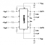
I've decided to give the LA6510 a try, basically just to see if I can even get it to simply work. That being said, the two thing I don't understand on this sample circuit in the datasheet are: the "Rsc" label which I'm unsure of it's meaning/function, and then what value one is suppose to use for all of the resistors that are marked 😕
And I truely do appreciate all the info though!
Attachments
Try this datasheet, it's not just a summary like the one you listed, it's from Sanyo:
http://semicon.sanyo.com/en/ds_e/EN2624E.pdf
It explains the values for Rsc at the end.
For all the other resistors, it just looks like a dual op-amp, so if you treat each half like an op-amp, the resistors would set the input impedance and the feedback (ie gain). You'll want the input resistors (+/- VIN1, VIN2) to be somewhere between 10k and 50k (try 25k to start?). Set the feedback resistor from that.
Here's a great site that gives an easy way to find the gain (among other things) for values of components:
Op-amp circuit analysis using a transfer function
Last edited:
Try this datasheet, it's not just a summary like the one you listed, it's from Sanyo:
http://semicon.sanyo.com/en/ds_e/EN2624E.pdf
It explains the values for Rsc at the end.
For all the other resistors, it just looks like a dual op-amp, so if you treat each half like an op-amp, the resistors would set the input impedance and the feedback (ie gain). You'll want the input resistors (+/- VIN1, VIN2) to be somewhere between 10k and 50k (try 25k to start?). Set the feedback resistor from that.
Here's a great site that gives an easy way to find the gain (among other things) for values of components:
Op-amp circuit analysis using a transfer function
Yea I had just came across that datasheet last night, which was 100x better than the previous one I had!! Not only was it current, but the images were clear and it provided far more info.
So I take it RSC is backwards for Current Sense Resistor? 😕 Sadly my current research has yet to bring me across items like that, but I'm hoping that link you posted will shed a lot of light on the subject, so I thank you for it 🙂
As far as resistors themselves though, I would've though to use 100Ω based on all the sample circuits in that datasheet 😱 Any reason not to use those listed in the samples?
Thanks again.
it sets the current from that extract. I had read that (without looking at the circuit) as source resistance
Last edited:
As far as resistors themselves though, I would've though to use 100Ω based on all the sample circuits in that datasheet 😱 Any reason not to use those listed in the samples?
Yes. Those samples are the circuits they used to measure the device's characteristics and are not functional for normal use. 100 ohms is WAY too low for the sources you would connect to an amp.
You are correct about Rsc. You should set the current limit fairly low to start with, then increase it after you are sure the circuit works.
Last edited:
- Status
- Not open for further replies.
- Home
- Amplifiers
- Chip Amps
- Change of gears. Going to start basic, need suggestions. (NOT a long post this time!)