Thanks everyone for comments and a great discussion.
The original challenge in the thread was to look at options for a direct drive of the midrange/treble in a QUAD ESL 57, which makes the voltage, current and capacitance numbers discussed above a bit less evil.
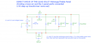
Member bazukaz has done a great LTSpice sim of the of the ESL57 internals.
see schematics below how a bridged amp could be connected (using his diagrams as a basis). As his simulation shows, there is xformer winding inductance, parasitic capacitance in the xformer windings that interact with the shown stock crossover components,
so with direct drive these components must for sure be changed (or even removed).
The original challenge in the thread was to look at options for a direct drive of the midrange/treble in a QUAD ESL 57, which makes the voltage, current and capacitance numbers discussed above a bit less evil.
Member bazukaz has done a great LTSpice sim of the of the ESL57 internals.
see schematics below how a bridged amp could be connected (using his diagrams as a basis). As his simulation shows, there is xformer winding inductance, parasitic capacitance in the xformer windings that interact with the shown stock crossover components,
so with direct drive these components must for sure be changed (or even removed).
Attachments
Thanks everyone for comments and a great discussion.
The original challenge in the thread was to look at options for a direct drive of the midrange/treble in a QUAD ESL 57, which makes the voltage, current and capacitance numbers discussed above a bit less evil.
Member bazukaz has done a great LTSpice sim of the of the ESL57 internals.
see schematics below how a bridged amp could be connected (using his diagrams as a basis). As his simulation shows, there is xformer winding inductance, parasitic capacitance in the xformer windings that interact with the shown stock crossover components,
so with direct drive these components must for sure be changed (or even removed).
I understand that you are puzzled , and every dilemma is worth investigation
I mostly joked , but as I see it - HV amp is full of compromises itself , so there is really a question - is that amount of compromises lesser evil than original matching xformer .....
if that question is so high on your priority list , as I said , you better be sure that you know what you're dealing with
any mistake can cost you much more than some gray smoke poofed from parts, as is case with "ordinary" amps
value of life is well worth stressing that once more
Member bazukaz has done a great LTSpice sim of the of the ESL57 internals.
see schematics below how a bridged amp could be connected (using his diagrams as a basis). As his simulation shows, there is xformer winding inductance, parasitic capacitance in the xformer windings that interact with the shown stock crossover components,
so with direct drive these components must for sure be changed (or even removed).
Mats do you also have typical values for those Ra resistors? I'd be interested in that simulated load for my own developments.
Jan
Wood chassis are good for HV projects. This project could be good just to learn how to deal with HV:
50,000V High Voltage Power Supply: 12 Steps (with Pictures)
50,000V High Voltage Power Supply: 12 Steps (with Pictures)
When I hooked it up to my powerhouse Sony TAN-7B everything sounded much better and cleaner. That TAN-7B produces 200W max and gobs of current.
But there are many differences between speakers and amps, especially current capacity, which may or may not follow from power rating. So you need to trial and error, or go with overkill just to be sure.
Jan
This whole thread inspired me to get my Quads back in service. (Still a ticking panel, but not too loud so I'll ignore it for now..) I've been using the ACA I just built with the SAL wideband drivers, and I left it in place. 8 watts, and it sounds fantastic driving the Quads! Sure, it's a bi-amped setup, and I wasn't listening at high volumes, but I was really impressed all in all. The ACA is more detailed than the tube amps I was using before with the Quads.
That said, I used to drive the Quads with a cheap muscle amp when I first got them in the 90s. That setup with the Quads on Arcici stands gave the cleanest, most musical bass... but the amp wasn't good enough in other respects.
I mostly joked , but as I see it - HV amp is full of compromises itself , so there is really a question - is that amount of compromises lesser evil than original matching xformer .....
The short answer is - I don't know , but I'm curious and it would be a fun and challenging project. Same reason why I don't stick with my commercial gear, but have built a bridged BA-1 SE monster, 4 channels of Aleph J's, 2 x BBA-3 and the LX Cross Over (and counting).
if that question is so high on your priority list , as I said , you better be sure that you know what you're dealing with any mistake can cost you much more than some gray smoke poofed from parts, as is case with "ordinary" amps
value of life is well worth stressing that once more
I value your concern about life, ZM, 😱 and it would be ridiculous response to say "I decided to not make any mistakes". Mistakes are made now and then.
As I mentioned earlier is quite dangerous to work with ESLs inside as well. (ESL 63's are even worse due to lots of HV cabling and solder pads carrying up to 6 kV accessible.)
Re. building an HV amp, I would think that some safety nets integrated in the design would be reasonable (build critical parts inside a sturdy plastic box, absolutely no HV on heat sinks (even inside the box), use protective zeners in critical places to guard against malfunction, use of corona laquer/double insulation, bees wax, add LED indicators "everywhere", use bleeder resistors, maybe even a relay that drops when mains is removed (or the lid of the HV box is opened) and connects low resistance bleeders to all critical 'lethal' points....and always keep one hand in your pocket 😛
I you remember old CRT-based TV-sets from the 60's-70's ---- they were pretty dangerous as well, 230 V AC mains voltage on all metal parts inside with 50% probability, 800-1000V exposed on top of PL36...PL509 tubes inside HV unit. 15 kV on top a DY87 rectifier....etc.
And yet here we are 😎
Mats do you also have typical values for those Ra resistors? I'd be interested in that simulated load for my own developments.
Will send you mail, Jan 🙂
Last edited:
Will keep everyone in suspense (including myself), but i did find a promising ESL direct drive design -- a class A circlotron using cascaded MOSFETs -- IXYS IXTH1N250 (Vdss max = 2.5 kV).
Output is +- 1kV peak (so about 6 db below maximum possible output from the ESL57s, but a good starting point to do A/B comparisons vs the transformer solution. Seems to be able to drive 1 nF with good slew rate so the ESL57 treble panel (300 pF) shouldn't pose a problem.
Will report back when prototype is up and running (measured FR, phase and distorsion characteristics using a B&K 4133 mic + subjective listening).
Unfortunately the lead delivery time of the output transistors seems to be >10 weeks (Mouser) 🙁 and they are expensive -- USD 30 each, need 4/channel).
You need to consider that the HV bias supply for ESL is somewhat safer to work with because it is current limited. An amplifier will be much more lethal.
4.5 kV parts have been commercially available since 2013. Obviously you have no idea on >1 kV project, big $$$. How much would the transformer, diodes, capacitor bank and HV meters cost? Do not try to cut any corner. Please remember, your lavish funeral service means nothing for you.
4.5 kV parts have been commercially available since 2013. Obviously you have no idea on >1 kV project, big $$$. How much would the transformer, diodes, capacitor bank and HV meters cost? Do not try to cut any corner. Please remember, your lavish funeral service means nothing for you.
Yes, there is another IXYS MOSFET with Vdss @ 4.5 kV.
On the contrary, I have all numbers for PSU components (transformers, CLC-config, and rectifiers) making up the needed two floating 1 kV supplies --- USD 850 in latest Mouser summary, but I neither thought nor implied that this would be a low-cost adventure... 😎
Obviously you have no idea on >1 kV project, big $$$. How much would the transformer, diodes, capacitor bank and HV meters cost?
On the contrary, I have all numbers for PSU components (transformers, CLC-config, and rectifiers) making up the needed two floating 1 kV supplies --- USD 850 in latest Mouser summary, but I neither thought nor implied that this would be a low-cost adventure... 😎
??? Just be extremely careful allright? Make sure you know what you are doing before actually doing it.... and they are expensive -- USD 30 each, need 4/channel).
Last edited:
- Status
- Not open for further replies.
- Home
- Amplifiers
- Pass Labs
- Challenge: Can an Aleph J-ESL be built?