Three things makes me ask this question (it is a challenge really).
If Mr. Pass himself would comment , I would be honoured.
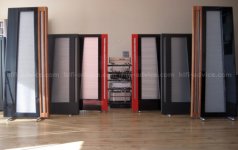
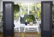
1. I'm totally impressed by the midrange/treble you get from the venerable QUAD ESL 57 (and other ESLs as well to some degree)
2. The Aleph J produces a very sweet and musical sound connected to ESL57s.
3. Still I would guess that the speaker transformer that converts the amp output voltage 1:270 for the bass panels and 1:90 for the midrange/treble panel does take away some of the potential sound quality.
Assuming that the midrange/treble is the most critical for perceived quality, how would an Aleph J-ESL be designed to 'direct drive' the midrange/treble part?
Very often midrange/treble protection is installed in these ESL57s to clamp the peak voltage to 2,200 Volts (using a chain of zeners), so that gives the amplifier peak voltage output needed to utilise the full (about) 103 dB potential.
So instead of +-24 Volts the Aleph J-ESL needs roughly a +- 2400 Volt PSU, scaling everything a factor of 100.
Cascaded expensive HV transistors, but maybe not more exotic than VFETs....how would it be designed?? Just a quick search gives STP4N150 - MOSFET N, 1500 V 4 A 160 W TO-220 @USD 6.00. Use of beeswax insulation (nice smell) and making ball-shaped solder connections to avoid corona discharge would bring a new dimension to Pass amps....
I'm fully aware that this thing would be totally lethal and also completely DIY-unfriendly. Bleeder resistors in the PSU would be a life vs. death detail....
But.... what don't we sacrifice for the ultimate sound experience?")
Curious,
/M
If Mr. Pass himself would comment , I would be honoured.
1. I'm totally impressed by the midrange/treble you get from the venerable QUAD ESL 57 (and other ESLs as well to some degree)
2. The Aleph J produces a very sweet and musical sound connected to ESL57s.
3. Still I would guess that the speaker transformer that converts the amp output voltage 1:270 for the bass panels and 1:90 for the midrange/treble panel does take away some of the potential sound quality.
Assuming that the midrange/treble is the most critical for perceived quality, how would an Aleph J-ESL be designed to 'direct drive' the midrange/treble part?
Very often midrange/treble protection is installed in these ESL57s to clamp the peak voltage to 2,200 Volts (using a chain of zeners), so that gives the amplifier peak voltage output needed to utilise the full (about) 103 dB potential.
So instead of +-24 Volts the Aleph J-ESL needs roughly a +- 2400 Volt PSU, scaling everything a factor of 100.
Cascaded expensive HV transistors, but maybe not more exotic than VFETs....how would it be designed?? Just a quick search gives STP4N150 - MOSFET N, 1500 V 4 A 160 W TO-220 @USD 6.00. Use of beeswax insulation (nice smell) and making ball-shaped solder connections to avoid corona discharge would bring a new dimension to Pass amps....
I'm fully aware that this thing would be totally lethal and also completely DIY-unfriendly. Bleeder resistors in the PSU would be a life vs. death detail....
But.... what don't we sacrifice for the ultimate sound experience?
Curious,
/M
Last edited:

2,200 V peak (4,400 Vpp) could be doable, not sure for 2,400 V peak (4,800Vpp)... Very often midrange/treble protection is installed in these ESL57s to clamp the peak voltage to 2,200 Volts (using a chain of zeners), so that gives the amplifier peak voltage output needed to utilise the full (about) 103 dB potential.
So instead of +-24 Volts the Aleph J-ESL needs roughly a +- 2400 Volt PSU, scaling everything a factor of 100. ...
Let's see how much sacrifice you are willing to do to reward the one who meets your challenge.... But.... what don't we sacrifice for the ultimate sound experience?
@
Yes, what I describe has been done with tubes (and with amazing results achieved -- at least stated as amazing). The challenge is how to build it with SS technology.
that Aleph could be best if built with GM70 or 845 in OS , with appropriate bottles in front
Yes, what I describe has been done with tubes (and with amazing results achieved -- at least stated as amazing). The challenge is how to build it with SS technology.
why?
horses for courses
I had my hands and head enough times inside of FM transmitter , equipped with mighty triode working on 3K5Vdc , so pretty much spent all of Exorcism I had left
though , I believe this place is wakoo enough** , so counting that you'll find accomplices for adventure ........
**reason why I'm furniture here
anyway , take care ....... to know what you're doing in every step ....
Are you posing a challenge or asking for a donation?... The challenge is how to build it with SS technology.
Are you posing a challenge or asking for a donation?
Just posing a challenge for a simulated design (eternal glory to the creator), and I volunteer to build a full scale prototype and report on results. Additional complexity on retaining frequency response since the xformer inductance plays a part in the crossover -- but that may be compensated in a preamp stage, i.e using the LX-mini crossover.
A designer in his right mind would never give a design that lethal to be built by a very eager kamikaze volunteer.... I believe this place is wakoo enough** , so counting that you'll find accomplices for adventure ........
very eager kamikaze volunteer
I decide to take that as a compliment ...
Of course I agree with the lethal aspects of it, although you have to work with exactly those voltages in ESL projects (ESL internals).
What if thinking outside a one amp box for a bit and compartmentalize the challenge.
Tesla uses almost the factor of 100 to scale up the voltage in a Model S
(small approx. 3.6 V Li-ion batteries (11*9) to achieve 375 V in a Model S)
A possible solution could be to reduce everything to 'normal' tube voltages or even lower (and closer to feasibility of a SS design) by having N small amps is series, each one producing 1/N Vpk), which reduces some of the need for exotic transistors and PSU capacitors and removes the lethal voltages in each compartment/module...and also reduces voltage gain need in each amplifier. The sum lethal voltage will exist only between the ESL + and - stators (exactly as with a standard ESL xformer solution). The need of floating inputs and floating PSUs will pose a challenge of course but should be solvable.
N to be chosen at the sweet spot of total system cost, non-lethality and 'not-too-exotic' SS design.
Since the power of each amp compartment/module (class A obviously) needs to be only in the 30/N W ballpark, the cost won't be too extreme.
Throwing in some numbers using a random number for N .... pick 15
Needed total series voltage 1500 Vrms (2100pk)
N=15 yields:
Output voltage/amp 100 Vrms (140 Vpk)
Rail voltage +- 150 V
Output power 2 W
Bias 30 mA (9 W/amp --- about 300 W for all amps and stereo, in the ballpark)
Gain 34 dB
Hopefully calculations make sense.
To paraphrase NP "This is the perfect high end audio product: Exotic, inefficient,
expensive" (although not unavailable and not toxic)
Last edited:

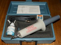
Everything gets complicated with voltages that high. Just to measure high voltages using a standard DMM? ….transformer, diodes, capacitors for the PSU, wire insulation that are 3k rated are the easy parts. High voltage probes for the oscilloscope…..like the one I have in the picture. It will be good to have some experience from the "tube-world" working with around 5-600 VDC before going for 3 kV. One mistake and there will be an awful smell of burnt meat
Attachments
- Status
- This old topic is closed. If you want to reopen this topic, contact a moderator using the "Report Post" button.
- Home
- Amplifiers
- Pass Labs
- Challenge: Can an Aleph J-ESL be built?