Three things makes me ask this question (it is a challenge really).
If Mr. Pass himself would comment , I would be honoured.
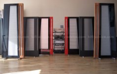
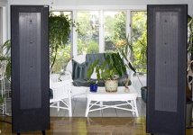
1. I'm totally impressed by the midrange/treble you get from the venerable QUAD ESL 57 (and other ESLs as well to some degree)
2. The Aleph J produces a very sweet and musical sound connected to ESL57s.
3. Still I would guess that the speaker transformer that converts the amp output voltage 1:270 for the bass panels and 1:90 for the midrange/treble panel does take away some of the potential sound quality.
Assuming that the midrange/treble is the most critical for perceived quality, how would an Aleph J-ESL be designed to 'direct drive' the midrange/treble part?
Very often midrange/treble protection is installed in these ESL57s to clamp the peak voltage to 2,200 Volts (using a chain of zeners), so that gives the amplifier peak voltage output needed to utilise the full (about) 103 dB potential.
So instead of +-24 Volts the Aleph J-ESL needs roughly a +- 2400 Volt PSU, scaling everything a factor of 100.
Cascaded expensive HV transistors, but maybe not more exotic than VFETs....how would it be designed?? Just a quick search gives STP4N150 - MOSFET N, 1500 V 4 A 160 W TO-220 @USD 6.00. Use of beeswax insulation (nice smell) and making ball-shaped solder connections to avoid corona discharge would bring a new dimension to Pass amps....
I'm fully aware that this thing would be totally lethal and also completely DIY-unfriendly. Bleeder resistors in the PSU would be a life vs. death detail....
But.... what don't we sacrifice for the ultimate sound experience? 🙂
Curious,
/M
If Mr. Pass himself would comment , I would be honoured.
1. I'm totally impressed by the midrange/treble you get from the venerable QUAD ESL 57 (and other ESLs as well to some degree)
2. The Aleph J produces a very sweet and musical sound connected to ESL57s.
3. Still I would guess that the speaker transformer that converts the amp output voltage 1:270 for the bass panels and 1:90 for the midrange/treble panel does take away some of the potential sound quality.
Assuming that the midrange/treble is the most critical for perceived quality, how would an Aleph J-ESL be designed to 'direct drive' the midrange/treble part?
Very often midrange/treble protection is installed in these ESL57s to clamp the peak voltage to 2,200 Volts (using a chain of zeners), so that gives the amplifier peak voltage output needed to utilise the full (about) 103 dB potential.
So instead of +-24 Volts the Aleph J-ESL needs roughly a +- 2400 Volt PSU, scaling everything a factor of 100.
Cascaded expensive HV transistors, but maybe not more exotic than VFETs....how would it be designed?? Just a quick search gives STP4N150 - MOSFET N, 1500 V 4 A 160 W TO-220 @USD 6.00. Use of beeswax insulation (nice smell) and making ball-shaped solder connections to avoid corona discharge would bring a new dimension to Pass amps....
I'm fully aware that this thing would be totally lethal and also completely DIY-unfriendly. Bleeder resistors in the PSU would be a life vs. death detail....
But.... what don't we sacrifice for the ultimate sound experience? 🙂
Curious,
/M
Last edited:
to make it short and sweet - take ordinary Aleph and connect it to Quad ESL57 inputs
then disconnect QuadESl57 panels and connect those wires directly to your ear lobes
experience will be even more direct , even with funny xformers still in picture

then disconnect QuadESl57 panels and connect those wires directly to your ear lobes
experience will be even more direct , even with funny xformers still in picture
Out of curiosity, for a panel that’s run from maybe 230hz on up, would 50-75 watts be sufficient for high SPLs?
Serbian electrocution. 🙂
Can I decide the tune... We will rock you//Queen to make it really short and sweet
🙂
Can I decide the tune... We will rock you//Queen to make it really short and sweet
🙂
2,200 V peak (4,400 Vpp) could be doable, not sure for 2,400 V peak (4,800Vpp)... Very often midrange/treble protection is installed in these ESL57s to clamp the peak voltage to 2,200 Volts (using a chain of zeners), so that gives the amplifier peak voltage output needed to utilise the full (about) 103 dB potential.
So instead of +-24 Volts the Aleph J-ESL needs roughly a +- 2400 Volt PSU, scaling everything a factor of 100. ...
Let's see how much sacrifice you are willing to do to reward the one who meets your challenge. 🙂... But.... what don't we sacrifice for the ultimate sound experience? 🙂 ...
@
Yes, what I describe has been done with tubes (and with amazing results achieved -- at least stated as amazing). The challenge is how to build it with SS technology.
that Aleph could be best if built with GM70 or 845 in OS , with appropriate bottles in front
Yes, what I describe has been done with tubes (and with amazing results achieved -- at least stated as amazing). The challenge is how to build it with SS technology.
why?
horses for courses
I had my hands and head enough times inside of FM transmitter , equipped with mighty triode working on 3K5Vdc , so pretty much spent all of Exorcism I had left
though , I believe this place is wakoo enough** , so counting that you'll find accomplices for adventure ........
**reason why I'm furniture here
anyway , take care ....... to know what you're doing in every step ....
Are you posing a challenge or asking for a donation?... The challenge is how to build it with SS technology.
Are you posing a challenge or asking for a donation?
Just posing a challenge for a simulated design (eternal glory to the creator), and I volunteer to build a full scale prototype and report on results. Additional complexity on retaining frequency response since the xformer inductance plays a part in the crossover -- but that may be compensated in a preamp stage, i.e using the LX-mini crossover.
A designer in his right mind would never give a design that lethal to be built by a very eager kamikaze volunteer.... I believe this place is wakoo enough** , so counting that you'll find accomplices for adventure ........
very eager kamikaze volunteer
I decide to take that as a compliment ... 😛
Of course I agree with the lethal aspects of it, although you have to work with exactly those voltages in ESL projects (ESL internals).
What if thinking outside a one amp box for a bit and compartmentalize the challenge.
Tesla uses almost the factor of 100 to scale up the voltage in a Model S
(small approx. 3.6 V Li-ion batteries (11*9) to achieve 375 V in a Model S)
A possible solution could be to reduce everything to 'normal' tube voltages or even lower (and closer to feasibility of a SS design) by having N small amps is series, each one producing 1/N Vpk), which reduces some of the need for exotic transistors and PSU capacitors and removes the lethal voltages in each compartment/module...and also reduces voltage gain need in each amplifier. The sum lethal voltage will exist only between the ESL + and - stators (exactly as with a standard ESL xformer solution). The need of floating inputs and floating PSUs will pose a challenge of course but should be solvable.
N to be chosen at the sweet spot of total system cost, non-lethality and 'not-too-exotic' SS design. 😉
Since the power of each amp compartment/module (class A obviously) needs to be only in the 30/N W ballpark, the cost won't be too extreme.
Throwing in some numbers using a random number for N .... pick 15 😉
Needed total series voltage 1500 Vrms (2100pk)
N=15 yields:
Output voltage/amp 100 Vrms (140 Vpk)
Rail voltage +- 150 V
Output power 2 W
Bias 30 mA (9 W/amp --- about 300 W for all amps and stereo, in the ballpark)
Gain 34 dB
Hopefully calculations make sense.
To paraphrase NP "This is the perfect high end audio product: Exotic, inefficient,
expensive" (although not unavailable and not toxic) 😀
Last edited:

Easier, so true and totally agree...but the space heaters produce midrange that challenges any 'proper speakers'...IMHO. 😎
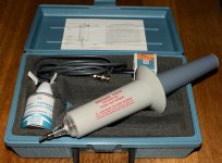
Everything gets complicated with voltages that high. Just to measure high voltages using a standard DMM? ….transformer, diodes, capacitors for the PSU, wire insulation that are 3k rated are the easy parts. High voltage probes for the oscilloscope…..like the one I have in the picture. It will be good to have some experience from the "tube-world" working with around 5-600 VDC before going for 3 kV. One mistake and there will be an awful smell of burnt meat 🙂
Attachments
- Status
- Not open for further replies.
- Home
- Amplifiers
- Pass Labs
- Challenge: Can an Aleph J-ESL be built?