That's probably how most people would do it. Like I said, it is just an experiment. Unless you're adventurous, you should probably keep C4 at 5pF if you build it.
- keantoken
- keantoken
Hi keantoken
Ok for me.
Thanx again for your help, I have to go sleep, early works tomorow.
Paul
Ok for me.
Thanx again for your help, I have to go sleep, early works tomorow.
Paul
Last edited:

Kean,
Take a look at the master, the NAD3020 phono stage from Tomlinson Holman, of THX fame. This was done on commission as he was completing his PhD about thirty years ago!!
Hugh
Hi People!
my 2 cents
this preamp is great sounding
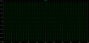
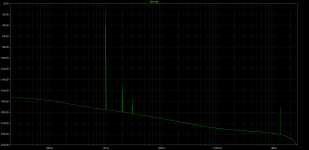
bellow are the sims (5mV at Vin):
Harmonic Frequency Fourier Normalized Phase Normalized
Number [Hz] Component Component [degree] Phase [deg]
1 1.000e+03 3.363e-01 1.000e+00 -51.28° 0.00°
2 2.000e+03 5.592e-08 1.663e-07 -93.29° -42.01°
3 3.000e+03 2.722e-09 8.093e-09 175.60° 226.88°
4 4.000e+03 1.528e-10 4.543e-10 77.64° 128.91°
5 5.000e+03 2.048e-10 6.088e-10 78.06° 129.34°
6 6.000e+03 2.638e-10 7.842e-10 78.44° 129.72°
7 7.000e+03 3.337e-10 9.921e-10 79.18° 130.46°
8 8.000e+03 4.136e-10 1.230e-09 79.91° 131.18°
9 9.000e+03 5.042e-10 1.499e-09 80.44° 131.72°
Total Harmonic Distortion: 0.000017%
Attachments
Since this time I've designed and built several amps all using the Rush cascode or NTP (no-tail pair). One significant appeal is that it requires less components, without needing a tail CCS.
Amazing how some things remain obscure, even for decades.
Amazing how some things remain obscure, even for decades.
there is some magic, for me, in the connection NPN emmiter to PNP emmiter (or vice versa);-)
it looks like NPN/PNP nonlinearities are good cancelled (how about N/P fets?)
maybe this is the way SSA thread was so popular?
it looks like NPN/PNP nonlinearities are good cancelled (how about N/P fets?)
maybe this is the way SSA thread was so popular?
The input of the NAD3020 phono stage is also known as a series differential pair.
As it is the same current which passes through each transistor, their non-linearites added and do not compensate as in a standard diff pair made of transistors of the same polarity.
A possible advantage of the series scheme is a better behaviour at high frequencies, thanks to the lack of parasitic capacitors due to the CCS at the emitters in the standard scheme (which behaves better at DC).
As it is the same current which passes through each transistor, their non-linearites added and do not compensate...
😕
why so low THD for 1kHz then, with 20kOhm load? (for 20kHz too)
😉
😕
why so low THD for 1kHz then, with 20kOhm load? (for 20kHz too)
😉
Did you measure it ?
The NTP does not cancel even harmonics like the LTP does. That does not mean it cannot give low distortion. I would give the circuit a chance. Cordell's models should be accurate enough if the simulation is set up well.
In most modern circuits the input stage is very lightly loaded, so it's the TIS and OPS that generate most of the distortion. For this reason a circuit may give the same THD regardless of NTP or LTP.
In most modern circuits the input stage is very lightly loaded, so it's the TIS and OPS that generate most of the distortion. For this reason a circuit may give the same THD regardless of NTP or LTP.
Member
Joined 2009
Paid Member
I've simulated NTP/LTP and found they behave more or less the same when the LTP is balanced. But the NTP has balance 'built-in' which can be an advantage. The NTP also has different characteristics at larger signal levels so it handles overload differently.
- Status
- Not open for further replies.
- Home
- Amplifiers
- Solid State
- CFP gain stage, modifications.