If we cannot make it work on the simulator it's much more unlikely to make it work on your custom designed PCB.
I agree with you Cortez. What should I change in the schematic than? Perhaps CCS is too weak? What if I use A1360\C3432 for CCS? Nor CCS transistors (little warm, as well as the input transistors), neither zeners arent geting hot during operation.
When I set the pots to 100R there are only 12.6V on zeners, on TLs - 11.6V. Obviously this is not a correct operation.
Can this be from a fake input transistors? Before when the first board had correct voltages I used another set of input transistors (from different seller).
Can I check a hFE of input transistors at 5 or 10mA of current, not just 1mA as in DMM hFE test? Perhaps this will reveal the problem?
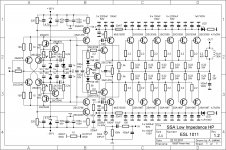
I found this schematic published by Lineup member.
Can this be from a fake input transistors? Before when the first board had correct voltages I used another set of input transistors (from different seller).
Can I check a hFE of input transistors at 5 or 10mA of current, not just 1mA as in DMM hFE test? Perhaps this will reveal the problem?
I found this schematic published by Lineup member.
Attachments
I never saw LC used this value in his schematics. Might I ask what do we accomplish by this? Voltage drop on 2.2K 2w was 30.5V.
I desoldered all 8 input transistors. First will try to power up and check without them.
Btw, before the fault IPS was working fine with all current values.
After powering up without 8 input transistors voltage drop on 15V zeners 11.05V\11.85V, on 2.2K2W - 26.7-26.9V with fronted PSU 42VDC. There must be something else which eating the current.
Last edited:
This mod will ensure that the zeners are fed with enough current so that when current is sourced from them, they don't sag the voltage (if they are not faulty).
In my SSA builds I always used 470R 1W resistors feeding 1N4744A zeners.
In my SSA builds I always used 470R 1W resistors feeding 1N4744A zeners.
4 2K2 0.5W got little hot, 45-50C I think, but voltage drop on 15V zeners was raising 14.6-14.7V\14.7-14.8V without input load.
Last edited:
4 2K2 0.5W got little hot, 45-50C I think, but voltage drop on 15V zeners was raising 14.6-14.7V\14.7-14.8V without input load.
Great!

Now see if the amp works with all the input transistors installed. If you see zener voltage dropping again, parallel one more 2K2 to each side.
edit: Not 2k2, that may cause overheating in zener. Try 4k7.
Last edited:
but something sags the voltage on zeners, I suspect VAS transistors. IPS should work on 2K2, as was before.
but something sags the voltage on zeners, I suspect VAS transistors. IPS should work on 2K2, as was before.
The VAS can only suck so much current as the two CCS allow. So I doubt the VAS transistors are to blame. See if the amp works with the input transistors installed with the parallel resistors in place. Show some pictures if possible.
The VAS can only suck so much current as the two CCS allow. So I doubt the VAS transistors are to blame. See if the amp works with the input transistors installed with the parallel resistors in place. Show some pictures if possible.
Than there is nothing left to blame who could suck so much current. Today I tried with new CCS transistors.
Attachments
![20170516_201348[1].jpg](/community/data/attachments/566/566119-693d2626a75832249811f48282e2b185.jpg?hash=aT0mJqdYMi)
![20170516_201958[1].jpg](/community/data/attachments/566/566135-eb17e9c5e1a75977646e80d5c96fe43a.jpg?hash=6xfpxeGnWX)
Last edited:
Thanks for the picture. Looks like the input transistors are not installed. Is the zener voltage still sagging after you paralleled the resistors?
Without input transistors perhaps not, I'm not sure if 14.7V is a little sag or not, but if paralleled 2K2 relatively hot, I guess there is a load and can be 0.2-0.3V sag. Perhaps they are hot from zeners.
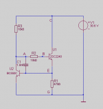
What will be if I remove VAS transistors 2SA1478\2SC3788 on the schematic with connected collectors of 2240\970 in removed transistors' place (take off 2SA1478\2SC3788 from the schematic) and power up without them as well? Other VAS transistors will survive?
What will be if I remove VAS transistors 2SA1478\2SC3788 on the schematic with connected collectors of 2240\970 in removed transistors' place (take off 2SA1478\2SC3788 from the schematic) and power up without them as well? Other VAS transistors will survive?
Last edited:
Without input transistors perhaps not, I'm not sure if 14.7V is a little sag or not, but if paralleled 2K2 relativly hot, I guess there is a load and can be 0.2-0.3V sag.
Ah. Okay.
Note that the 4V7 and 15V zeners Are the loads for these resistors. And this heating is completely normal. 14.7V is fine and with a 4K7 added to each parallel resistor bank it might rise to 14.9V.
Nothing else is loading the zeners or the parallel resistors and everything is normal. Install all input transistors and turn it on.
What will be if I remove VAS transistors 2SA1478\2SC3788 on the schematic and power up without them as well? Other VAS transistors will survive?
No need. Without the input transistors installed there is no drive current to the VAS so they are off.
I'll try to power up with all transistors in place and report back.
However I don't understand how to explain such big change in resistors' value. A mistake?
If I connect directly to PSU: 4.7V zener-2K2-15V zener-15V zener-2K2-4.7V zener, such approach won't show correct voltage drop on zeners as well?
However I don't understand how to explain such big change in resistors' value. A mistake?
If I connect directly to PSU: 4.7V zener-2K2-15V zener-15V zener-2K2-4.7V zener, such approach won't show correct voltage drop on zeners as well?
I'll try to power up with all transistors in place and report back.
However I don't understand how to explain such big change in resistors' value. A mistake?
I'm not sure. However, zeners have a minimum bias current for normal operation. It changes with voltage rating and wattage of the zener. In this application and with the 5W zeners 2K2 seems inadequate to me after going through the datasheet.
If I connect directly to PSU: 4.7V zener-2K2-15V zener-15V zener-2K2-4.7V zener, such approach won't show correct voltage drop on zeners as well?
This approach would show correct zener voltages but as soon as you externally (like through a CCS) draw current from the zeners the voltage will drop if you do not bias the zeners appropriately.
This approach would show correct zener voltages but as soon as you externally (like through a CCS) draw current from the zeners the voltage will drop if you do not bias the zeners appropriately.
Direct connect to PSU of these components string gives the same voltage drop - 14.7V\14.8V on zeners, 2K2 are little warm.
If VAS and CCS have no load, can they draw such current in the idle? I'm still confused because before the IPS worked with single 2K2 resistors.
Shaan, can I used 4K7 1W or 0.5W on the OPS instead of 2W types? How to determine optimal BE resistors value on the drivers, which currently 33R?
Last edited:
- Status
- Not open for further replies.
- Home
- Amplifiers
- Solid State
- CFP Amplifier - Help Please!