
I agree, the waves look good. I will try to get it hooked up to my A/B setup in the next day or two. I want to hook it up to a smaller PSU so I can let it play for a while. Right now it is being fed by my variac through a big PSU.
BTW, I used BC546C/556C. The amp is very quiet. It does have a nasty turn on thump. Likely because of all the large caps that have to charge. A speaker protection with delayed on will take care of it.
Hi Terry,
If you have time would you mind doing an experiment for me with the gate stoppers? A smaller value will result in a better steeper square wave. Can you find out if a lower value like 10R or 22R can still work? I believe the sound will be better with a smaller value, assuming it can suppress the instability.
Thanks,
X
.....suppress the instability.....
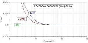
Hi X speculate in that the other simple builds of this amp didn't seem to have instability problems. Could be wrong but besides your current trim open up higher bandwidth than the other simpler builds yours is the first seen that i know of have 100nF implemented into feedback network. Many runs with only one 2,2mF elco and even Lazy Cat's VSSA 1.4 that have in sim and theory bandwidth up in 2,7mHz area can live with 2,2mF elco alone but he recommend for sound quality also add one 10uF MKT film. So think it could be that 100nF that makes a VHF low impedance high Q resonance path that push to instability point, and it would be easy to try without this 100nF or add some small resistance in series and see if instability improves.
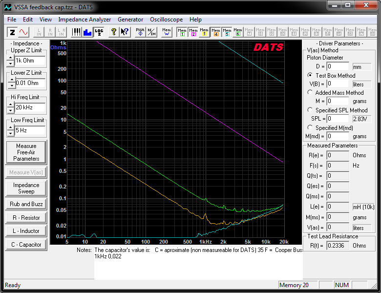
Can myself only measure up to 20kHz with DATS device but below show that nothing is linear as we would like.
BLUE: 100nF Panasonic film ECWFD PP RM:10mm
PURPLE: 10uF Wima film MKS RM:15mm
GREEN: 2,2mF Nichicon FG RM:5mm
ORANGE: 6,8mF Panasonic FR RM:5mm
BLUE: 35F COOPER Bussmann HV RM:7,5mm
Also here is some AC documentation for capacitor networks:
http://www.diyaudio.com/forums/powe...ing-psu-capacitors-effective.html#post1566979
http://www.diyaudio.com/forums/powe...g-psu-capacitors-effective-2.html#post1567402
I only use metal thin film 1% resistors unless 5w cement power units which are wire wound heaters I think and 5%. Even as large as 2w I use metal thin film 1%.
The critical ones that need to be 1% metal thin film are probably ones that control bias on input stage and VAS stage. Feedback should also be 1% to ensure even gain on split to upper and lower paths.
The critical ones that need to be 1% metal thin film are probably ones that control bias on input stage and VAS stage. Feedback should also be 1% to ensure even gain on split to upper and lower paths.
Last edited:
Byrtt,
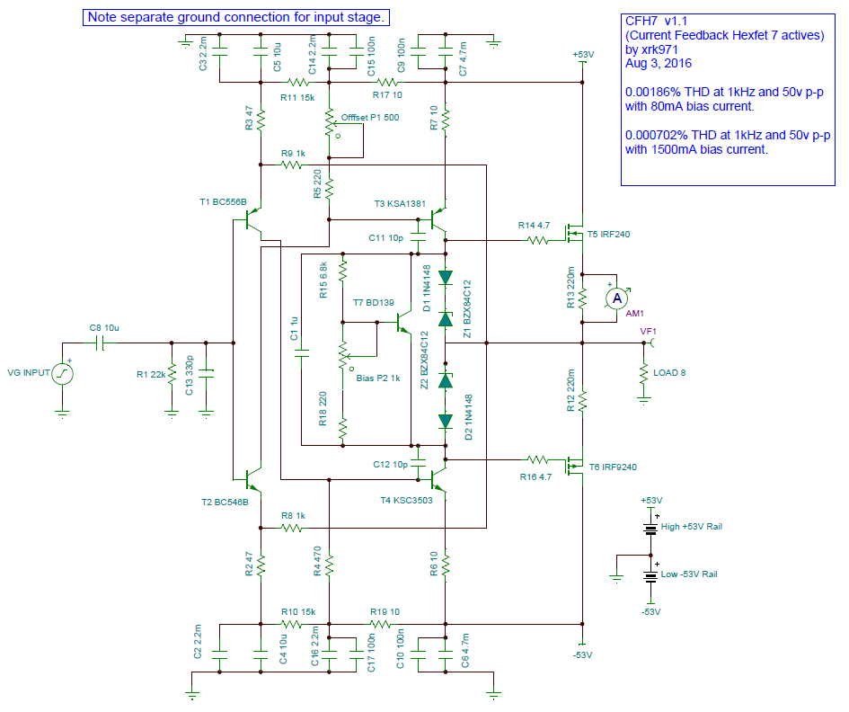
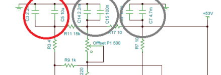
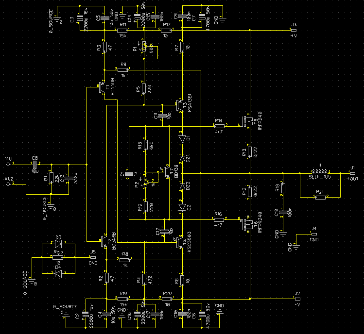
Which 100nF cap are you referring to that is in the feedback network?
Ha ha will wash my mouth because haven't looked into your original schematic until now, but only looked at the various builds and it looks like now, that except layout by idefixes all others include a 100nF in feedback network as seen below (100nF/10uF/2,2mF in parallel).
Attachments
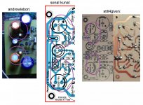
Ha ha will wash my mouth because haven't looked into your original schematic until now, but only looked at the various builds and it looks like now, that except layout by idefixes all others include a 100nF in feedback network as seen below (100nF/10uF/2,2mF in parallel).
Interesting that Sonal added the 100nF bypass cap on top of the 10uF bypass already added to the 2200uF elco already there as the mail input stage supply rail. I don't think the 100nF is in the feedback path as it supplies the rails for the input stage via the 47R current limiting resistors.
But, yes, my schematic doesn't have that 100nF cap there. It's on the middle VAS supply rail cap though.
Byrtt,
Thanks for the DATS impedance plots of various caps. You are right, most of my caps seem to follow the green line (1000uF, 2200uF and 4700uF no name brands) and end up with circa 0.05ohm ESR at 10kHz and around 5ohm to 10ohms at 10Hz. So for deep bass, the amp impedance will probably be limited by this - unless very large dia copper wire runs from main PSU is provided.
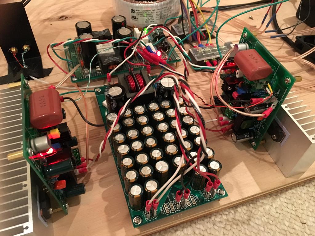
However, if one uses something like this and thick copper wire between it and amp, very low ESR is possible - about same as source resistors - circa 0.25R. Here I use qnty 20 x 1000uF caps plus a 4700uF cap per rail:
Thanks for the DATS impedance plots of various caps. You are right, most of my caps seem to follow the green line (1000uF, 2200uF and 4700uF no name brands) and end up with circa 0.05ohm ESR at 10kHz and around 5ohm to 10ohms at 10Hz. So for deep bass, the amp impedance will probably be limited by this - unless very large dia copper wire runs from main PSU is provided.
However, if one uses something like this and thick copper wire between it and amp, very low ESR is possible - about same as source resistors - circa 0.25R. Here I use qnty 20 x 1000uF caps plus a 4700uF cap per rail:
xrk971,
Thanks share 20 x 1000uF pcb and its data it looks nice and cool.
Can it be right i think from your latest two post that you read C2/4 and C3/5 little wrong : ) as being part of supply rail but its the ones called feedback capacitors. Try in your TI TINA sim and pull out C6/7/9/10/14/15/16/17 which all belong to supply rails and nothing will change in new sim because TINA's power supply is perfect clean and don't need those caps as we do need in real world, then try pull C2/3/4/5 and amp wont swing AC anymore. Thats why i care impedance without resonance for that feedback capacitor network position, well wish it to be linear which it isn't in real world as seen in DATS plots that can't show inductance reality for large elco's above 20kHz, only TINA think so and simulate with a perfect linear 2,2mF capacitor. Also if you bypass your input coupling capacitor C8 with a wire amp will still have lagging time domain in lows and high pass function in amplitude domain because ruled by actual value of feedback capacitor network, even there is no coupling cap in hot signal route. More info for those feedback capacitor network is if you bridge two amps then don't couple feedback caps to ground but use only one set of feedback caps on one amp and cross wire it to same point on the other amp so its a virtual floating ground.
Attachments
Byrtt,
You are right - I usually think of the "feedback cap" as called the "shunt capacitor" and on a differential LTP input, it is connected to the two feedback resistors with the shared point of the two resistors connected to the negative side transistor base of the LTP, with the positive of the elco shunt cap connected to the smaller value resistor. With gain equal to ratio of two resistors (numerator being one connected to output stage). In the case of a singleton input stage, the current feedback here does indeed get connected to the caps which looks like a rail cap for the resistor-based input stage current source, but also serves double duty as the feedback shunt cap. Here, the lower the ESR, the better the bass response. Gain on this amp is 1k/47R or about 21x or 26.4dB, a bit lower than usual 30dB power amp gains that I usually see around here.
You are right - I usually think of the "feedback cap" as called the "shunt capacitor" and on a differential LTP input, it is connected to the two feedback resistors with the shared point of the two resistors connected to the negative side transistor base of the LTP, with the positive of the elco shunt cap connected to the smaller value resistor. With gain equal to ratio of two resistors (numerator being one connected to output stage). In the case of a singleton input stage, the current feedback here does indeed get connected to the caps which looks like a rail cap for the resistor-based input stage current source, but also serves double duty as the feedback shunt cap. Here, the lower the ESR, the better the bass response. Gain on this amp is 1k/47R or about 21x or 26.4dB, a bit lower than usual 30dB power amp gains that I usually see around here.
Last edited:
I think it is R10 & R11 that are causing the confusion.
Are they a positive feedback to help with setting input offset? The two emitters have to be held off signal ground by one Vbe each.
If one were to set these two to infinity, the feedback route looks completely conventional: output>1k0>feedback node>47r>signal ground/return.
Are they a positive feedback to help with setting input offset? The two emitters have to be held off signal ground by one Vbe each.
If one were to set these two to infinity, the feedback route looks completely conventional: output>1k0>feedback node>47r>signal ground/return.
Last edited:
Good point AndrewT. In the simulation, I find that too large of a value of R10/11 did in fact affect the DC offset stabilization time constant. Too low and ability to keep up with square wave was affected. It may be source of turn on thump.
xrk971,
Good to get sorted so we now talk the same.
Makes me think about you most have thought i was bit crazy to care so much for elco impedance used in supply rails : )
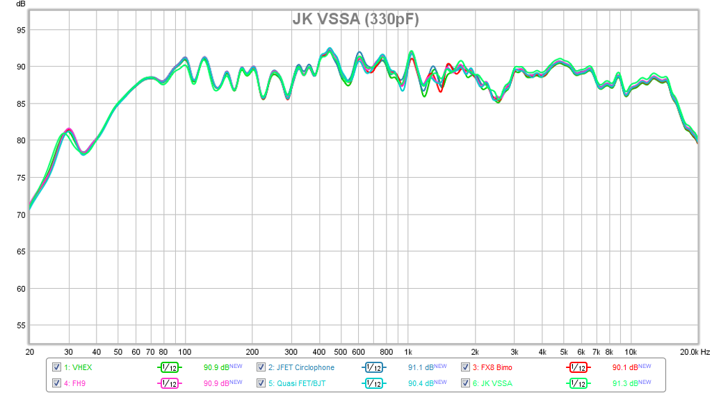
When we now talk same you maybe better understand my post over your virtual audition thread too where pointed to the small but audioable broadband HF lift seen for your JK VSSA build compared to rest of the amps at that time. Repost plots below to show it looks like frq dependent lowest impedance spike for 2,2mF green trace cover that little bit boosted area. In sim where frq dependent feedback cap have lowest impedance output amplitude will be hottest, that's why I wrote that maybe the 100nF paralleled SMD resistor still4given had below PCB could be some the culprit to instability that was tamed with gate stoppers that you didn't like because in sim it killed HQ square waves.
Good to get sorted so we now talk the same.
Makes me think about you most have thought i was bit crazy to care so much for elco impedance used in supply rails : )
When we now talk same you maybe better understand my post over your virtual audition thread too where pointed to the small but audioable broadband HF lift seen for your JK VSSA build compared to rest of the amps at that time. Repost plots below to show it looks like frq dependent lowest impedance spike for 2,2mF green trace cover that little bit boosted area. In sim where frq dependent feedback cap have lowest impedance output amplitude will be hottest, that's why I wrote that maybe the 100nF paralleled SMD resistor still4given had below PCB could be some the culprit to instability that was tamed with gate stoppers that you didn't like because in sim it killed HQ square waves.
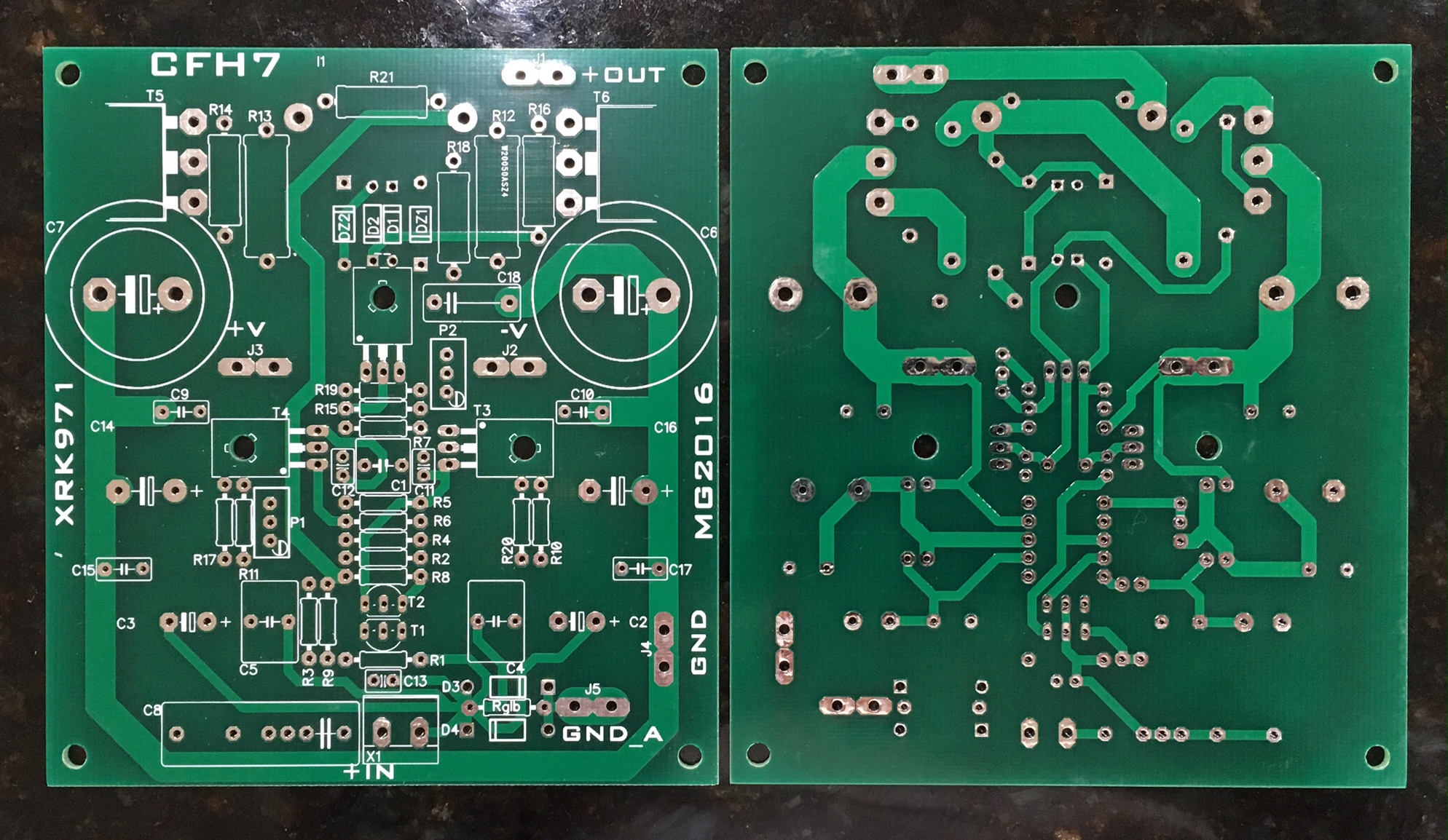
CFH7 PCB's arrived
This is the Idefixes design v1. Looks great - but looks like a drill thru-hole for securing MOSFET heatsink is missing. I can manually drill that I suppose. Looks like a straight forward build though.
Gerbers for this board can be found here:
http://www.diyaudio.com/forums/solid-state/294834-cfh7-amp-11.html#post4795571
I believe this is the parts stuffing guide then:
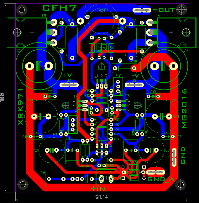
Attachments

Last edited:
Update: no hole needed for MOSFET heat sink - it hangs out the side enough that a hex ball driver can be angled to secure screw. A Dremel tool could be used to cut a half round notch to fit a standard screwdriver. Not quite far in enough to drill a hole - just a small notch is needed.
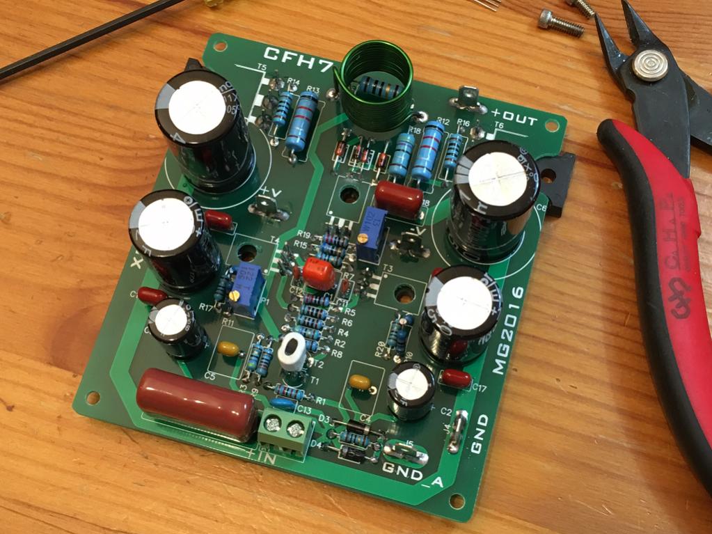
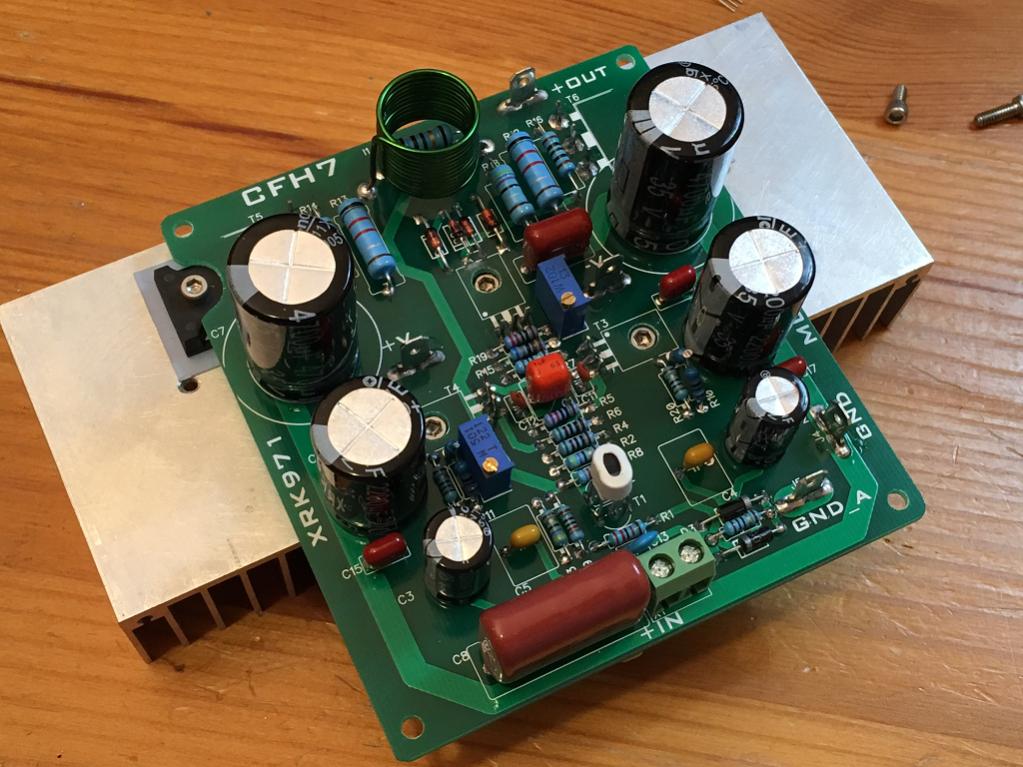
Build progress
Making progress on the build, one amp is done and other just requires installation of transistors. Initial test the Vbe multiplier works and bias current can be set to almost any arbitrary value. I have it at 150mA now. However, I cannot zero out the offset. It bottoms out at 0.88v. I will have to figure out if I need a bigger or smaller value pot for the DC offset.
Maybe it is related to the inability to set DC offset close to zero, but there is 60Hz hum on this amp. Seems like there is a ground loop on the input stage? Will need to look at it with fresh eyes tomorrow but if anyone has ideas? Not sure why the 500R pot + 220R does not seem to be balanced by 470R resistor. The pot has to be set to zero ohms to get the offset low as possible. Note that I even matched Hfe of the input transistors BC546 and BC556 bot with Hfe=375. Feedback resistors are 820R instead of 1k (ran out of 1k and I could use a little more gain). Also, using 1000uF instead of 2200uF feedback shunt caps (ran out of 2200uF's).
Or is this hum caused by the big U shaped ground bus making a loop around the input stage?
Frontside:
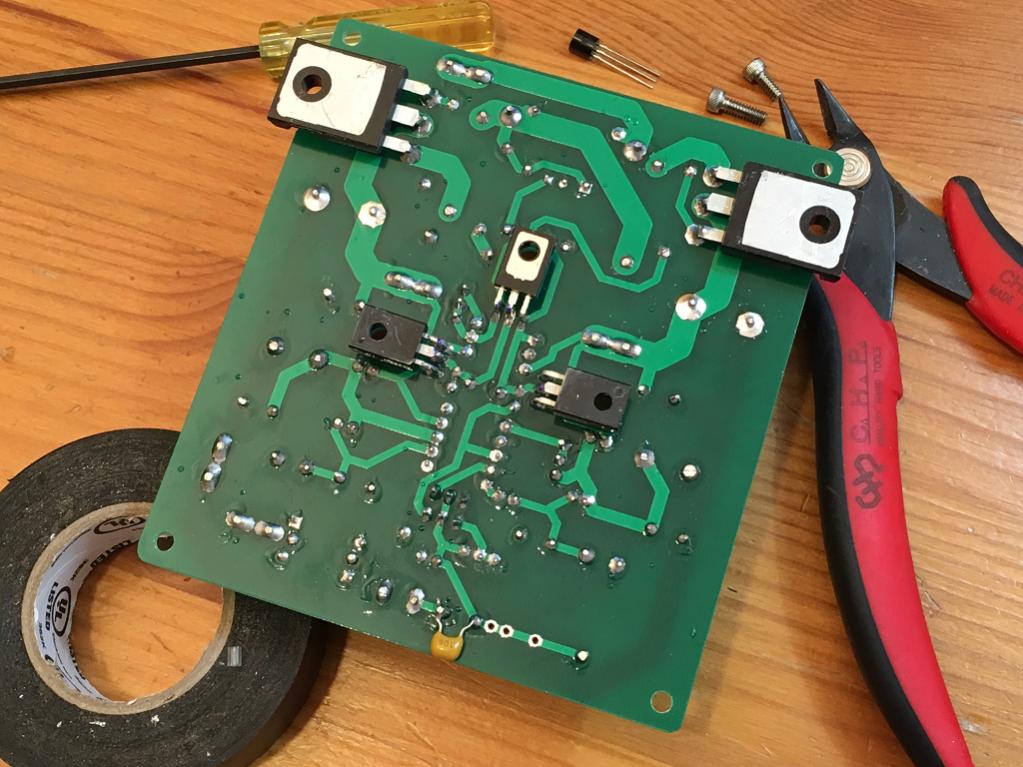
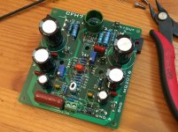
Backside:
Mounted on heatsink:
Making progress on the build, one amp is done and other just requires installation of transistors. Initial test the Vbe multiplier works and bias current can be set to almost any arbitrary value. I have it at 150mA now. However, I cannot zero out the offset. It bottoms out at 0.88v. I will have to figure out if I need a bigger or smaller value pot for the DC offset.
Maybe it is related to the inability to set DC offset close to zero, but there is 60Hz hum on this amp. Seems like there is a ground loop on the input stage? Will need to look at it with fresh eyes tomorrow but if anyone has ideas? Not sure why the 500R pot + 220R does not seem to be balanced by 470R resistor. The pot has to be set to zero ohms to get the offset low as possible. Note that I even matched Hfe of the input transistors BC546 and BC556 bot with Hfe=375. Feedback resistors are 820R instead of 1k (ran out of 1k and I could use a little more gain). Also, using 1000uF instead of 2200uF feedback shunt caps (ran out of 2200uF's).
Or is this hum caused by the big U shaped ground bus making a loop around the input stage?
Frontside:
Backside:
Mounted on heatsink:
Attachments


Last edited:
- Home
- Amplifiers
- Solid State
- CFH7 Amp