Good reading
Hi All,
Just came across material at Intersil (chip manufacturer) web site I find interesting.
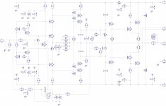
CFA amp topology with high slew rate in mind. Interesting use of current mirrors. This is actually a video-amp, but never mind.
Parameters table, comparing a number of CFA and one VFA designs - well, practically confirms what we already know about the pros and cons of both approaches.
(Parameters CFA, VFA)
And some theory-related reading from Intersil, including SPICE macromodel of the amp mentioned above.
(Documentation)
Have fun 😉
Hi All,
Just came across material at Intersil (chip manufacturer) web site I find interesting.
CFA amp topology with high slew rate in mind. Interesting use of current mirrors. This is actually a video-amp, but never mind.
Parameters table, comparing a number of CFA and one VFA designs - well, practically confirms what we already know about the pros and cons of both approaches.
(Parameters CFA, VFA)
And some theory-related reading from Intersil, including SPICE macromodel of the amp mentioned above.
(Documentation)
Have fun 😉
Attachments

Nice one, dadod ! I like an amplifier to have 20KHz of open loop bandwidth.This is with lateral MOSFET OPS and JFET input, not so low distortion, but simpler and according to the simulation very stable.
Damir
Last edited:
This is with lateral MOSFET OPS and JFET input, not so low distortion, but simpler and according to the simulation very stable.
Damir
Damir, looks not bad at all. Would dynamic load instead of R5, R6 improve distortion situation? I mean, did you try to simulate it with CCS's?
Damir, looks not bad at all. Would dynamic load instead of R5, R6 improve distortion situation? I mean, did you try to simulate it with CCS's?
Thanks Valery, yes I tried but the problem is that there is only 2 V drop and not easy to have a good CCS(I mean real CCS not the one from the LTspice library) working with so low voltage, and I've got much higher distortion. I will tray with GainWire input stage instead, but then it's not simple any more.
One think is important here that it's not easy to match the complementary JFETs, and here I used possibility to adjust R47 first before the DC servo was connected, otherwise with high DC offset at the output DC servo could not catch. Instead R47 could be a trim pot used, or better adjust the DC offset with the trimmer, unsolder it, measure the value and solder a resistor close to the measured value, then connect the DC servo.
OK great news. It just needed to be done to be complete and sure and know. THx-Richard Marsh
Richard and all, I think I understood my "mistake" here. I mean, we need to understand what to measure, having the complex load.
We need to measure frequency response not in terms of amplitude at the output, but in terms of current through the speaker coil. Current - is what actually produces the sound and what will be rather different in a complex load environment comparing to purely resistive one.
Am I right?
P.S. Will run some tests with regards to this in the evening.
Hi, vzaichenko.
Just think of an amplifier with a high Z output. What do you measure ? Distortion of the speaker ?
We used in our R&d office, for our own minds, to look at square waves and measure distortions of our amp's prototypes at their outputs with a real speaker charge (A very high power one in a dumped and isolated room). Not achievable everywhere and very boring, just imagine the painful noise during hours despite the isolation.
And as all the speaker's loads are all very different, no way to publish 'comparable' measurements from various manufacturers, unless all of them agree on a 'standard' charge (impossible).
Right, but what happened with the different amplifiers, running with the same speaker? This is something I want to explore.
It is complicated to resume. Mostly a question of feedback ratio, damping factor ;-)Right, but what happened with the different amplifiers, running with the same speaker? This is something I want to explore.
May-i suggest you, sorry for the off topic, to forget about this and try to linearize you speaker's impedance (both Zobel and motional) as i do ?
Last edited:
Well, ok - this is actually an ultimate goal of the whole exercise 🙂
Also (as it definitely depends on feedback ratio, output impedance, etc.) it will be interesting to see if there will be significant difference in achieving such linearization for CFA and VFA designs.
What do you mean by "motional" BTW?
Also (as it definitely depends on feedback ratio, output impedance, etc.) it will be interesting to see if there will be significant difference in achieving such linearization for CFA and VFA designs.
What do you mean by "motional" BTW?
For point one, i don't think there is a difference between CFA and VFA in regerd the way they drive Speakers, as long as their characteristics are close.it will be interesting to see if there will be significant difference in achieving such linearization for CFA and VFA designs.
What do you mean by "motional" BTW?
('Motional' compensation is linearizing impedance at the resonance frequency of all the speakers in a multi-way system before applying filters. A Serial resonant RCL network, parallel to the divers's coils. Zobel is to compensate the reactance of the coils. The goal is to have a flat impedance curve equal to the DC resistance of the coil.)
Last edited:
Thanks Valery, yes I tried but the problem is that there is only 2 V drop and not easy to have a good CCS(I mean real CCS not the one from the LTspice library) working with so low voltage, and I've got much higher distortion. I will tray with GainWire input stage instead, but then it's not simple any more.
One think is important here that it's not easy to match the complementary JFETs, and here I used possibility to adjust R47 first before the DC servo was connected, otherwise with high DC offset at the output DC servo could not catch. Instead R47 could be a trim pot used, or better adjust the DC offset with the trimmer, unsolder it, measure the value and solder a resistor close to the measured value, then connect the DC servo.
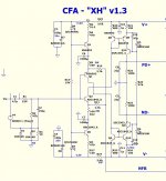
I have also designed a "simplified" version of CFA amp (comparing to the initial design) over the weekend. IPS is pretty much inspired by the GainWire with some modifications. Trans-impedance stage - "traditional" cascoded VAS - proven performance in a number of my previous designs. Finally, EF3 with Sziklai OPS.
Looks very good in simulator - waiting for PCB manufacturing to see it live...

Attachments
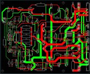
I have also designed a "simplified" version of CFA amp (comparing to the initial design) over the weekend. IPS is pretty much inspired by the GainWire with some modifications. Trans-impedance stage - "traditional" cascoded VAS - proven performance in a number of my previous designs. Finally, EF3 with Sziklai OPS.
Looks very good in simulator - waiting for PCB manufacturing to see it live...
Could you show some simulated data, distortion, loop gain, square wave...?
That looks familiar 🙄 .I have also designed a "simplified" version of CFA amp (comparing to the initial design) over the weekend. IPS is pretty much inspired by the GainWire with some modifications. Trans-impedance stage - "traditional" cascoded VAS - proven performance in a number of my previous designs. Finally, EF3 with Sziklai OPS.
Looks very good in simulator - waiting for PCB manufacturing to see it live...
I see the "evil diamond" , the low voltage stages/CCS ....
even the inverting servo trimming the High-Z input.
... = my first "NAD/gnome ????
The same cascoded VAS ... but you added a cascode to the low-Z stage
(CFB).
Thimios built it ... it is good , works as simulated.
PS - no Re on Q5/6 ? it might be a little "psycho" (unstable?)
OS
Last edited:
Thank you vzaichenko !
Your shunt comp. of the VAS works better than
the standard forum method ....
I also see how you could "get away" with no Re. (CLG is
trimmed with the R/C shunt).
I added this to the "Cat's" VSSA/Hawksford (below) ... much reduced
higher order distortion.
I am beginning to prefer the 1 stage CFA approach , simple ...
no servo , nothing to "slow it down" (500V/uS) 😀 .
OS
Attachments
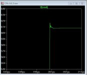
Nope ... absolutely
700V/us with just a bit of ringing (below) - Much better method ! 🙂🙂
OS
!nothing to "slow it down"
700V/us with just a bit of ringing (below) - Much better method ! 🙂🙂
OS
Attachments
Thank you vzaichenko !
Your shunt comp. of the VAS works better than
the standard forum method ....
I also see how you could "get away" with no Re. (CLG is
trimmed with the R/C shunt).
I added this to the "Cat's" VSSA/Hawksford (below) ... much reduced
higher order distortion.
I am beginning to prefer the 1 stage CFA approach , simple ...
no servo , nothing to "slow it down" (500V/uS) 😀 .
OS
Hi OS, BTW I also tried mirroring the IPS output current to VAS, but in my case simulation showed the same performance from just resistors there, so I kept them for simplicity.
On the other hand, cascoded VAS performs mush better than the one without cascode (for a number of reasons), but this was already confirmed by a number of previous designs.
Compensation - yes, I experimented with different approaches - this one shows good performance. In the previous design I used Miller compensation, ended up with 2.2pF in each shoulder (in the live prototype)... very light one.
"Evil diamond" allows avoiding electrolytic caps - something I always try to do unless there is a very good reason for using them.
My previous prototype shows some 360nS raise/fall at 20V amplitude - more than enough for accurate sound reproduction 😉
I like your designs - normally very refined ones

OS,
So a new version of the CFA-X now an XH! Simpler is nice if it works better and from what you and Vzaichenko are saying it sounds like it could be a real audio improvement. I have to go send some money to Jason for two of the output section boards and still waiting and watching on the input section side.
A question about the output side, What would the estimated output of the boards be with only two output devices running something like 50v rails? I know I won't need anywhere near the full output of the 5 pairs design for my application and in the end it would make a smaller board with a few of the output device positions loped off. The voicecoil I am using in my speaker is only rated 150watts max and you'll never get there so even 150 watts is going to drive you out of a room with loads of headroom, so no clipping expected ever really.
Hi OS, BTW I also tried mirroring the IPS output current to VAS, but in my case simulation showed the same performance from just resistors there, so I kept them for simplicity.
On the other hand, cascoded VAS performs mush better than the one without cascode (for a number of reasons), but this was already confirmed by a number of previous designs.
Compensation - yes, I experimented with different approaches - this one shows good performance. In the previous design I used Miller compensation, ended up with 2.2pF in each shoulder (in the live prototype)... very light one.
"Evil diamond" allows avoiding electrolytic caps - something I always try to do unless there is a very good reason for using them.
My previous prototype shows some 360nS raise/fall at 20V amplitude - more than enough for accurate sound reproduction 😉
I like your designs - normally very refined ones
Thank you again ... On the VSSA (for some reason ?) , using miller comp. did
not bring "much to the table" while using the hawksford
.... like for the leach VFA or the "2 stage CFA".
Mirroring the hawksford (and using shunt comp.) allowed for that 700V+
(.1us for my full rail to rail 😱) The resistor was a tad slower.
The mirror also makes it a little more "rail independant" with different
supply voltages.
As far as the caps ..... it is a trade-off between offset/simplicity.
The caps allow for much less "imbalance" between the P-N input pair to
get low offset (look at the CCS's in my schema) ... 1.8ma for one , 1.86ma for the other.
I do simulate slightly higher LF THD .... but we are more sensitive
to 500hz - 10K anyway ("stellar" 10ppm performance here).
16 devices = 10ppm (the "spooky leach" VFA)
10 devices = 10ppm (this CFA).
Sounds like a good deal. It should really appeal to new builders.
BTW - no hawksford /miller comp = 40ppm+
Hawksford + shunt = 10 ... same amp. 🙂
OS
Last edited:
OS,
So a new version of the CFA-X now an XH! Simpler is nice if it works better and from what you and Vzaichenko are saying it sounds like it could be a real audio improvement. I have to go send some money to Jason for two of the output section boards and still waiting and watching on the input section side.
A question about the output side, What would the estimated output of the boards be with only two output devices running something like 50v rails? I know I won't need anywhere near the full output of the 5 pairs design for my application and in the end it would make a smaller board with a few of the output device positions loped off. The voicecoil I am using in my speaker is only rated 150watts max and you'll never get there so even 150 watts is going to drive you out of a room with loads of headroom, so no clipping expected ever really.
2 OP pairs would be like my HK680 (90w 8R - 130+ 4R) .. it has 52V rails.
Don't underestimate 90W - I'm using my 680 to test my 10" tangband wt644f
and am getting the FULL 10mm Xmax from the "lowly" HK @ 25hz !
OS
Ohh.. I see somebody found the trick to mirror the current into the VAS, this also prevents thermal drift of the VAS current. Distortion goes down as the current is no longer modulated over the rail resistor. To me this is a much better structural amplifier.
This is very similar to the CFA models. I have been building.
I would let the CCS transistors Q3,Q6 be a parts of a current mirrors and then set the driving current through a floating CCS, where I also would inject the servo.
This is very similar to the CFA models. I have been building.
I would let the CCS transistors Q3,Q6 be a parts of a current mirrors and then set the driving current through a floating CCS, where I also would inject the servo.
Last edited:
- Home
- Amplifiers
- Solid State
- CFA Topology Audio Amplifiers