


Biasing with diodes ---
[ as usual, if too small - Click on picture then magnify/zoom in]
View attachment abcdef.pdf
Thx-RNMarsh
[ as usual, if too small - Click on picture then magnify/zoom in]
View attachment abcdef.pdf
Thx-RNMarsh
Last edited:
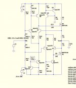
here's the 7000$ amp's OPS ...
Dirt cheap MPSA's + IRFP's ...😀
LOTS of heat !!!
OS
Do they use a single IRF pair in the commercial version or a few parallel pairs?
O-stripper, could you post the .ASC file for the burning amp.... I would like to fiddle with it and bring to more moderate levels of dissipation
no oscillations ??
triple (below 1) puts out wave (below 2) into 1u/2r load.
I can't get this triple to oscillate - whatever I do !
20 different input stages - the OPS NEVER misbehaves ....
OS
Dear OS,
could you post the complete design's asc file so I can try my bjt models?
Thanks, Toni
If fets have mostly 2H ... assuming.... the ops fets are easier in a differential or push-pull amplifier to cancel their dominate harmonics.... esp 2H. In either case, what is the easiest way to cancel that pesky 3H in an OPS? ... at the OPS.
Thx-RNMarsh
You are somebody.
Do you mean crossover or compressive gain? Both are thirds
Do you mean crossover or compressive gain? Both are thirds
gain. Was thinking rossover but gain too. How do you get rid of the 3rds typically.Or conceptually.
-RM

Hi Guys
It has been stated many places that in complimentary circuits it is important to either match devices in comp positions, or match the gain of the two circuit halves, or both. In many instances, matching beta cuts distortion by ten times, witness the output transistor data sheet for MJL21193/4 where a basic open-loop EF exhibits 0.8% THD but matching gains cuts it to 0.08%.
I believe similar results occur with comp diff front-ends.
The 1381-3503 pair is used in a lot of simulated amps, usually with the C gain range. Supposedly, someone sells these through ebay - a place I'll never buy products from - and legit suppliers like Digikey and Mouser only stock the KSA-KSC form which happen to come in different gain ranges. if one was really lucky, buying 1k of each device there could potentially be about 20% that overlap, assuming an even distribution of devices over their respective gain ranges. So, the only way around the beta dilemma is to cascode these devices with others that can be matched. This is quite a shame since the beta curves for these BJTs is very flat.
I asked Damir about this and he suggested I field it here.
In the simulations for any of the CFAs presented here, has anyone tried changing the betas of the complimentary positions where the 1381-3503 are? The 1381 is available in the E gain range: 100-200, and the 3503 as D: 60-120. Maybe because these are used in the VAS their beta only effects low-frequency gain. But... in a CFA that high low-f gain extends upward higher in frequency than in a VFA with miller compensation, so beta could make a difference to the circuit symmetry.
As an aside: Even with an Audio Precision THD analyser there would be no way to actually measure Damir's circuit apart from seeing that its THD cannot be resolved. AP is working on a software upgrade to extend resolution.
Richard: The schemo in post-4388 looks essentially like the heart of a CFA. Do you have a link to the text that goes with this?
Have fun
Kevin O'Connor
Do they use a single IRF pair in the commercial version or a few parallel pairs?
4 fully separate amps like in my post , paralleled.
Rated at 200W/8R - 800W/2R ... one big class A !!
The input is derived from the secondary of a jensen audio transformer.
I used the 2 diodes to emulate the voltages I read from that small trafo (RNmarsh).
OS
.asc's
Below are the 2 class A's (new one and ... the "genesis")
and the EF3.
Interesting ....THD20 of -
.08 for my new class A.
.0009 for the "genesis" .... (it seems to have OP device error correction !)
and , a healthy .018% for the EF3 (biased at 72ma).
All @ 80v p-p , 20k/8R
PS- I did not include models ... y'all want to use your own , anyhow.
OS
Attachments
When I first reverse engineered it , it was one of 4 paralleled amps.
Forgot to switch it for stand alone operation.
(below) , I scaled it to a 2 pair IRFP 4R/200W class A.
..... still a nice .003% THD20 -4R.
CCS's needed more (I) for stability. 🙂
edit- broke out into oscillation as soon as it left class A !
PS - this is my oldest simulation - I knew very little in 2008 😱 😱 .
OS
Attachments
Last edited:
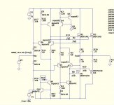
Genesis CFA ??
😀😀 Looks good , VSSA + genesis OPS.
The Vbe here can set FET bias between 3 - 6A and will thermally
stabilize the OPS. The real genesis did this plus used a computer
to allow remote control of the class A bias with a control voltage.
R45 = 0R=5.7A to 500R= 3.1A.
PS - H2 dominant and real stable (SW).
OS
Attachments
Now your talkin. Add body to the wonderful dynamic capability of your amps.I simulate my triples at 2R . Even as I never expect this , I'll get "anal" and
go for 1 or lower. Just a slightly larger "suckout" cap at the driver stage.
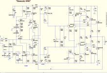
On a different tangent , anyone ever tried a class A OP on a CFA ?
Here is one (below) that is quite promising. H2 only and total THD20 about
as low as my standard EF3 (w -gnfb).
OS
WOW ! .001/1K and .006 THD20 at 125V p-p/4R
A "pass killer" 😀 . CFA , as well !
Edit - 3 pair IRFP @ 60V will be enough SOA to have a "badger class" 150W class A. (just looked up IRFPxxx)
You would need 7A per rail continuous - 800VA 45-0-45V trafo per channel.
OS
A "pass killer" 😀 . CFA , as well !
Edit - 3 pair IRFP @ 60V will be enough SOA to have a "badger class" 150W class A. (just looked up IRFPxxx)
You would need 7A per rail continuous - 800VA 45-0-45V trafo per channel.
OS
Attachments

Last edited:
Hi Guys
Is no one up to the task?
From my previous post:
"In the simulations for any of the CFAs presented here, has anyone tried changing the betas of the complimentary positions where the 1381-3503 are? The 1381 is available in the E gain range: 100-200, and the 3503 as D: 60-120."
Have fun
Kevin O'Connor
Hi Guys
It has been stated many places that in complimentary circuits it is important to either match devices in comp positions, or match the gain of the two circuit halves, or both.
As an aside: Even with an Audio Precision THD analyser there would be no way to actually measure Damir's circuit apart from seeing that its THD cannot be resolved. AP is working on a software upgrade to extend resolution.
Richard: The schemo in post-4388 looks essentially like the heart of a CFA. Do you have a link to the text that goes with this?
Have fun
Kevin O'Connor
In practice, i always select/match complimenets and get my lowest distortion. Wouldnt be too hard in SIM to do a mont-carlo on the beta and see what happens.
Which Audio-Precision? The 2722... that would be great for me if it was that model.
no link... as you can see from the example (LF351), it is a very old idea; One of the benefits of collecting circuits for a long time. I believe you can find it on the Internet... it was in a circuits idea collection. I used the idea a few years ago in a Power Amp front end with a better IC OPA, of course, with excellent results. Works very well and cuts costs and size.... a long time favorite area of interest for me... thus, the reason I saved it.
THx- Having fun.
RNMarsh
Last edited:
When I first reverse engineered it , it was one of 4 paralleled amps.
Forgot to switch it for stand alone operation.
(below) , I scaled it to a 2 pair IRFP 4R/200W class A.
..... still a nice .003% THD20 -4R.
CCS's needed more (I) for stability. 🙂
edit- broke out into oscillation as soon as it left class A !
PS - this is my oldest simulation - I knew very little in 2008 😱 😱 .
OS
Thanks for that.
Any ideas on why it oscillated? Comp of the class A control Amp?
The nice thing about these techniques is you don't need to accurately match halves - that's a real benefit for MOSFET output stages.
Last edited:
- Home
- Amplifiers
- Solid State
- CFA Topology Audio Amplifiers