😀A perfectly isolated servo from the signal path will have no effect on the output offset at all.
I meant they were sure to know little and have a lot to discover.Besides, it doesn't always help to be modest
😀
I meant they were sure to know little and have a lot to discover.
Yes , lots to discover ! Many "guru's" around here. (mine the guru's 😉 )
OS
I think it was Scott who said 'Leave no Guru unstoned'. 😀
Anyway, I promised to put up some sim results on the GM and PM comparison between a CFA and VFA.
These are basic amplifier models and these sims were done for investigative purposes only and to get a bit more insight into the differences between the two - and especially so after we have seen a lot of CFA designs closing the loop at 3,4 and 5 MHz and still stable. I wondered what was going on here. Seems actually, you can do this with a CFA and for good technical reasons.
😎
Attachments
I think it was Scott who said 'Leave no Guru unstoned'. 😀
Anyway, I promised to put up some sim results on the GM and PM comparison between a CFA and VFA.
These are basic amplifier models and these sims were done for investigative purposes only and to get a bit more insight into the differences between the two - and especially so after we have seen a lot of CFA designs closing the loop at 3,4 and 5 MHz and still stable. I wondered what was going on here. Seems actually, you can do this with a CFA and for good technical reasons.
😎
Can you plot VFA decreased open loop gain to 72dB like CFA?
"Rumble" plots ....
As you all know , the VFA vs. CFA "war" will be determined - one way or another.
I simulated .. not just generic designs , but "tweaked ones" ..
Bonsai's conclusions do come true in the plots here , as well.
Both amps are set to 28db gain.
THD is simulated at 3R load - 1/2 power ... same EF3 at 78ma bias.
The first 2 (below 1+2) are the CFA NAD/w-servo 🙄 .
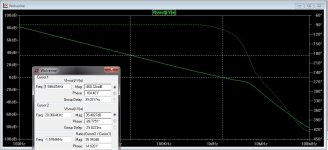
UG at 3mhz , an extra 13db (41db total) of available NFB gain at 20Khz.
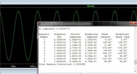
It manages 8ppm in this configuration. 1K THD is similar.
The second pair of attachments (below 3-4) is the "evil"
 VFA..
VFA..
The "poor thing" only has a few DB of extra gain at 20K ... even as it is
"juiced"... to a healthy 1.5mhz ULGF.
One would think it could not match the mighty CFA with double digit gain...
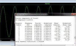
but , it BEATS it ! (attachment 4).
The VFA must be more effective at correction , even with less gain
(a few db .. even).
(below 5) ... the VFA "walks all over" the CFA at 1K , having both more gain
and more effective cancellation.
OS
As you all know , the VFA vs. CFA "war" will be determined - one way or another.
I simulated .. not just generic designs , but "tweaked ones" ..
Bonsai's conclusions do come true in the plots here , as well.
Both amps are set to 28db gain.
THD is simulated at 3R load - 1/2 power ... same EF3 at 78ma bias.
The first 2 (below 1+2) are the CFA NAD/w-servo 🙄 .
UG at 3mhz , an extra 13db (41db total) of available NFB gain at 20Khz.
It manages 8ppm in this configuration. 1K THD is similar.
The second pair of attachments (below 3-4) is the "evil"
VFA..The "poor thing" only has a few DB of extra gain at 20K ... even as it is
"juiced"... to a healthy 1.5mhz ULGF.
One would think it could not match the mighty CFA with double digit gain...
but , it BEATS it ! (attachment 4).
The VFA must be more effective at correction , even with less gain
(a few db .. even).
(below 5) ... the VFA "walks all over" the CFA at 1K , having both more gain
and more effective cancellation.
OS
Attachments


Last edited:
Yes. And then you get better gain and phase margins.
Your statements earlier in the thread are now making sense to me. Have you updated the VFA vs CFA paper on your website yet?
PS. I agree with you that there's more to this than just loop gains. It just seems to me to be an "advantage" of VFA that keeps getting repeated.
The servo control signal is best injected at CCS or place buffered/isolated from ac signal path. Thx-RNMarsh
Makes me wonder whether this where autobias circuits could come in handy here. Could these be used to control DC offset? Haven't got the knowledge to work out how this could be done though.
Congrats.to get a bit more insight into the differences between the two
Bob Cordell (3866)
Hi Petr,
Thanks for clarifying. I guess I was implicitly assuming that the resistance of quality speaker cable of reasonable length would be less than 0.1 ohm.
Hello, Bob !
In my practice, there was a case when the 200 Hz square wave instead of the expected 2000 A for the calculation was obtained by short-circuit current is only 300 A, 7 times less . But even if we assume that the first harmonic is 70%, then the current had to be at least 1400A .
I believe that the main reason for the skin effect . In order not to alter the transformer output voltage is rectified near the transformer. After rectification with regard to large losses diode managed to get a short-circuit current of 600 A, two times more than those without rectification.
So real resistance speaker cables considering skin effect and proximity effect conductors at least 1.5 ... 2 times more purely ohmic .
regards
Petr
Your statements earlier in the thread are now making sense to me. Have you updated the VFA vs CFA paper on your website yet?
PS. I agree with you that there's more to this than just loop gains. It just seems to me to be an "advantage" of VFA that keeps getting repeated.
Yes it's not straight forward. If you want lowest THD, then VFA is probably the way to go, although we've seen some designs here that really do achieve very good performance in that regard. However, if you get low THD in a CFA by raising the OLG, you end up with the same margin issues and performance more like a VFA in that regard.
So, for me it's not so much about a rumble, but it's a bit more nuanced than that
😀
Article is not updated yet - probably next weekend.
As you all know , the VFA vs. CFA "war" will be determined - one way or another.
I simulated .. not just generic designs , but "tweaked ones" ..
Bonsai's conclusions do come true in the plots here , as well.
Both amps are set to 28db gain.
THD is simulated at 3R load - 1/2 power ... same EF3 at 78ma bias.
The first 2 (below 1+2) are the CFA NAD/w-servo 🙄 .
UG at 3mhz , an extra 13db (41db total) of available NFB gain at 20Khz.
It manages 8ppm in this configuration. 1K THD is similar.
The second pair of attachments (below 3-4) is the "evil"
The "poor thing" only has a few DB of extra gain at 20K ... even as it is
"juiced"... to a healthy 1.5mhz ULGF.
One would think it could not match the mighty CFA with double digit gain...
but , it BEATS it ! (attachment 4).
The VFA must be more effective at correction , even with less gain
(a few db .. even).
(below 5) ... the VFA "walks all over" the CFA at 1K , having both more gain
and more effective cancellation.
OS
Good analysis OS. I agree if you want lowest THD, then VFA is the way to go.
Petr, as said Bob, The good enclosure's manufacturers use to tune their bass reflex with burned speakers... average cables...and average amplifiers.So real resistance speaker cables considering skin effect and proximity effect conductors at least 1.5 ... 2 times more purely ohmic .
For they are tuned more or less correctly for much of the customers.
Not to forget the impedance of the serial inductance(s) of the bass speaker's filter.
Every added (or subtracted) resistance change the QTS of the speaker.
Like him, i don't see the advantage of a negative amplifier impedance. Kind a servo attempt ?
That is for sure in simulations. Not so obvious in real world measurements in the upper range. ;-)I agree if you want lowest THD, then VFA is the way to go.
I cannot explain why, but, on my experience, well designed CFAs measure often better than expected. LC can confirm, who else ?
For VFA, an effect of the non matched tranies in the LTP ?
Last edited:
Esperado (3894)
Not to forget the impedance of the serial inductance(s) of the bass speaker's filter.
Every added (or subtracted) resistance change the QTS of the speaker.
Like him, i don't see the advantage of a negative amplifier impedance. Kind a servo attempt?
Esperado!
I have great respect for you as a specialist and your statements. Less than six months after the publication of my article how to open a branch on the amplifier:
Íîâûé óñèëèòåëü Ïåòðîâà . - Ñòðàíèöà 2
have repeated the first rave reviews. So do not dismiss him as from the past stage.
Regards
Petr
Oh, just questions, no statements. I just try to understand, i'm curious...I have great respect for you as a specialist and your statements.
Tried to read your link, Petr., as Russian is Hebrew for me, but, with Google traduction, it looks like people talking about cooking and specially ham ;-)
I don't see any reason why simulation would not be able to demonstrate this effect, if it exists.
You are making an extraordinary statement, so you'd better come up with solid arguments about. Unfortunately, so far, your descriptive explanation doesn't make any sense, and simply starting with "Bob I agree with you" doesn't help. Mr. Cordell was talking about a lead-lag compensation at the VAS output. As I mentioned myself, that's a Miller loop compensation aide and has nothing to do with the shunt dominant pole that you are wrongly promoting as the holy grail for CFAs.
You already got the explanation why the shunt compensation is suboptimal, all is needed is you to read it and digest it.
Now go ahead and start ranting.
Actually its you thats ranting, youre missing the whole point. I know exactly what Bob meant, the discussion wasnt about using shunt in VFA where it is suboptimal and should only be used as an aid. The benefit of having a shunt aid is already built-in in a CFA design.
Is this so hard to understand or should I draw you some pictures.
Shunt is only suboptimal when used in VFA design, in CFA its a different matter. Did you miss the part about the open loop gain too ??.
You should go study Sassens analysis regarding the use of shunt compensation.
BTW Im still waiting for you to post a CFA opamp that doesnt use shunt compensation.
I don't even understand the subject. For me, the only question is "Are-we running out of current, there ?". What did i have missed ?the discussion wasnt about using shunt in VFA where it is suboptimal and should only be used as an aid.
Is this so hard to understand or should I draw you some pictures.
Yes please, that's all I'm asking. Please prove that shunt compensation is optimal for CFAs.
Name dropping doesn't count.
You are here in front of a lot of great audio designers. They all know what you just have learned at school or in books: A theoretical knowledge, just information, not knowledge, a very little part of the game.
I don't even understand the subject. For me, the only question is "Are-we running out of current, there ?". What did i have missed ?

No, we are not running out of current.
- Home
- Amplifiers
- Solid State
- CFA Topology Audio Amplifiers