Distortion, bandwidth and slew rate are all knobs the designer can adjust in the design process. There is no correlation beyond a certain point that driving any of these parameters in excess will deliver a 'better' amplifier. This forum is full of earnest efforts to get to 1 ppm distortion and less, more often than not at the expense of huge complexity, or compromises elsewhere in the design like stability for example.
When we stop this numbers chasing game, and instead focus on more balanced designs, we will make progress again. Not before then.
What do you mean by "balanced" designs ?
Do blameless amps belong to this category ?
Balanced in terms or distortion, stability, bandwidth and SR.
Distortion 1%, DC offset 300mV, bandwidth 30khz, SR 1V/uS. This is balance design, I think...😉
About VAS input, despite some comments of contributors that i prefer to ignore, it is a very interesting place to investigate an amplifier, on my point of view.
- Looking at sinus wave forms, and with a little habit, you can have a good feeling of the kind of non linearities the amp produce in open loop, including the OPS (remember you look here at signal+err correction).
- With a sweeping frequency, you'll got an idea of where your feedback ratio stops to be linear (Flat open-loop bandwidth limit) without any complicated set-up. This is interesting in relation to the slew rate.
If a 20K signal is there 12db higher than the 100Hz one for the same input level, it is obvious that we will need the slew rate to be 4 time higher than the minimum requested to don't add distortion to the error correction. We have to remember that VAS is the place where most of the gain is produced, and, if at its input 20Khz signal is 12db higher, this stage will have to amplify 4 times this input signal.
- Using a musical signal, it is interesting to see how a real loudspeaker is changing the amp behavior: You will probably see the peak levels for the same musical sample being higher (and the need of higher slew rate accordingly too).
All this together can explain why some prefer higher slew rates than the theoretical 'enough' one ;-).
I remember the first time i tuned my protection prototype idea. (it compare input and output signal). While it was stable at any frequency with sinus and resistive load, my protection fired at the first kick drum at an average level.
I realized my good measuring amplifier was... not so good when it is about to play real music (transients) on real loads.
Now, i use-this kind of comparator often, listening to the output of my comparator, to isolate and lighten distortion. If it sounds horrible, there is luck your amp will sound this way.
Oh, yes, we don't want our amps to have too much a 'character' ;-)Balanced in terms or distortion, stability, bandwidth and SR.
Balanced in terms or distortion, stability, bandwidth and SR.
Do not forget : noise, Power Supply Rejection, Common Mode Rejection, DC offset stability, output impedance, overshoot with square waves on capacitive loads, and much more.
But you do not define what you mean by "balanced".
Last edited:
I remember the first time i tuned my protection prototype idea. (it compare input and output signal). While it was stable at any frequency with sinus and resistive load, my protection fired at the first kick drum at an average level.
I realized my good measuring amplifier was... not so good when it is about to play real music (transients) on real loads.
This could be a useful instrument (sanity check) in design.
Do not forget : noise, Power Supply Rejection, Common Mode Rejection, DC offset stability, output impedance, overshoot with square waves on capacitive loads, and much more.
But you do not define what you mean by "balanced".
Of course.
I think you know exactly what I mean. And especially so after my explicit clarification.
About VAS input, despite some comments of contributors that i prefer to ignore, it is a very interesting place to investigate an amplifier, on my point of view.
- Looking at sinus wave forms, and with a little habit, you can have a good feeling of the kind of non linearities the amp produce in open loop, including the OPS (remember you look here at signal+err correction).
With a sweeping frequency, you'll got an idea of where your feedback ratio stops to be linear (Flat open-loop bandwidth limit) without any complicated set-up. This is interesting in relation to the slew rate.
If a 20K signal is there 12db higher than the 100Hz one for the same input level, it is obvious that we will need the slew rate to be 4 time higher than the minimum requested to don't add distortion to the error correction. We have to remember that VAS is the place where most of the gain is produced, and, if at its input 20Khz signal is 12db higher, this stage will have to amplify 4 times this input signal.
Douglas Self wrote something like this in 1993, and it still features in the sixth edition of his book (p199) :
At first it appears axiomatic that the stage providing all the voltage gain of an amplifier is the prime suspect for generating a major part of its non-linearity. In actual fact, though the distortion behaviour of the simple VAS may be complicated, it can be made too linear to measure [...]
I think amplification with negative feedback is a highly counter-intuitive science.
Due the low open-loop bandwidth of the LM4562, its VAS signal of is certainly a lot more awful than most power amps. However it is currently among the best op-amps currently available and has the reputation among the audiophiles not to impose any footprint to the signal (which may not what they desire, but that's another story).
Bob Cordell's quoted paper deals with that.With a sweeping frequency, you'll got an idea of where your feedback ratio stops to be linear (Flat open-loop bandwidth limit) without any complicated set-up. This is interesting in relation to the slew rate.
If a 20K signal is there 12db higher than the 100Hz one for the same input level, it is obvious that we will need the slew rate to be 4 time higher than the minimum requested to don't add distortion to the error correction. We have to remember that VAS is the place where most of the gain is produced, and, if at its input 20Khz signal is 12db higher, this stage will have to amplify 4 times this input signal.
A large open loop bandwidth means a design restricting the open loop gain at low frequencies which could safely applied to linearise the whole circuit. In general the current needed to charge and discharge compensation capacitors is the same in both cases :
- open loop with low gain and large flat bandwidth, which provides artificially limited performances
- open loop with high gain and limited flat bandwidth which provides better overall performances
Both designs can have the same maximal slew-rate which is not a feature related to open loop bandwidth.
Being higher than what ?- Using a musical signal, it is interesting to see how a real loudspeaker is changing the amp behavior: You will probably see the peak levels for the same musical sample being higher (and the need of higher slew rate accordingly too).
Examples ?
Modern amplifiers show maximal slew-rates about 30 times, or much more, than the theorically needed one.All this together can explain why some prefer higher slew rates than the theoretical 'enough' one ;-).
Of course.
I think you know exactly what I mean. And especially so after my explicit clarification.
No. I can only suppose you mean that there are compromises to do between the various performances. For example, more maximal slew-rate at the expense of a bit more THD. But we can increase the maximal slew-rate without touching the THD (but, perhaps, the noise will increase...).
I notice the nay sayers are remarkably silent on their own 'real life' or even SPICE world designs.
How about posting some of YOUR own efforts and some CONSTRUCTIVE explanation of why they are better than our cr*p designs instead of your usual vitriol, idle speculation and dogma.
No, he can not. He is a professional not a DIY'ers. Maybe his work just patented. Or maybe he just created snake oil....
Of course, the one which provide the lowest output impedance in open loop ?Here is where we can answer - which output stage configuration is best? Is it the OPS which reduces that signal to the lowest level at VAS - without causing other serious issues.
Mean some OPS with local feedback ? I'm not at all experienced in multiple feedback topologies.
Richard, let-me explain for people who don't understand the phenomena. When the speaker produce a current, this current is seen at the input of the feedback path. Return to the input stage -input, is amplified by the VAS (in phase opposition) then the OPS, and this signal try to null the one from the speaker. That is the reason high feedback ratios will produce better damping factor. . I hope i'm clear.
Some unwashed people or some my contradictors, believe that an amp with a damping factor of 100 will reduce this voltage by the same factor. It is true, looking at the output. Not at the VAS input, as this output impedance *is an effect of the feedback*.
Like said one of them, feedback is counter intuitive ;-)
In the example i provided, the level of the signal at VAS is ~1/4 of the one we could see with an input witch gives the same 10V at output on a resistive load.
Results are predictable, but I will try to do a sim (let me some time). Well, it will be a sim for a speaker with a glued moving coil ;-). Unless one of my contradictors pretending a speaker is easy to model can provide-me a model with EMF and CEMF .Can you apply the same generator (phase) to the input and the output and see how that forward signal is altered at VAS by the reverse signal gen applied at the output? [Did I say that clearly?] And again with frequency from low to high. With resistive load and with reactive speaker simulated circuit for load.
The best would be to make real measurements with real speakers.
1-Yes, Richard. The difference is PSR is nulled in the traditional VFA differential input stage. But the same in VAS, because VAS are the same in both topologies.1-I'm going to go out on a limb (only cos I haven't investigated in detail) and claim that Wahab's "less efficient for power supply rejection" is simply due to the symmetrical topologies most CFAs are based on.
2- Anyone want to show PSR of symmetrical VFA & CFAs of equal complexity without 'low noises PSUs' and other fancy rubbish? We'll allow the VFA a headstart of 1 extra device .. OK 2 devices but no more.
2- I had done a comparison here, previously published in this thread:
http://www.esperado.fr/temp/VSSA/vssa-vs-vfa.html
Adding 2 cap multipliers (one for+V, one for-V) to the VAS+input stage (~15-20mA), two transistors, means equal number of tranies with the VFA (the two extra in the LTP), and the PSRR will be better in the CFA, both common and differential.
Last edited:
More Myth busting -
OPS ---- what is the difference using a SIM in the Isolation from output to VAS input with generator on output.... the OPS with [single pair] power bipolar or power FET?
-RNM
OPS ---- what is the difference using a SIM in the Isolation from output to VAS input with generator on output.... the OPS with [single pair] power bipolar or power FET?
-RNM
Last edited:
 Stick to technical arguments. Failure to follow this directive will result in a read-only vacation.
Multiple posts have been deleted.
kgrlee said:
- I'm going to go out on a limb (only cos I haven't investigated in detail) and claim that Wahab's "less efficient for power supply rejection" is simply due to the symmetrical topologies most CFAs are based on.
- Anyone want to show PSR of symmetrical VFA & CFAs of equal complexity without 'low noises PSUs' and other fancy rubbish? We'll allow the VFA a headstart of 1 extra device .. OK 2 devices but no more.
Thanks for this, Christophe.
- Yes, Richard. The difference is PSR is nulled in the traditional VFA differential input stage. But the same in VAS, because VAS are the same in both topologies.
- I had done a comparison here, previously published in this thread:
http://www.esperado.fr/temp/VSSA/vssa-vs-vfa.html
Adding 2 cap multipliers (one for+V, one for-V) to the VAS+input stage (~15-20mA), two transistors, means equal number of tranies with the VFA (the two extra in the LTP), and the PSRR will be better in the CFA, both common and differential.
Just to recap the CFA Myths that this thread has busted
- Noise? Simple CFAs are quieter than VFAs
- THD? Several CFAs presented here rival more complex VFAs
- PSR? Better or no worse as Christophe shows. This myth is caused by symmetrical topologies NOT by CFAs.
- For simple amplifiers, CFAs are better on ALL the usual performance parameters at equal or less complexity
- Easy zillion V/us slew
C'mon Mr. Cordell. One of my obvious aims is to persuade you to do more than damn CFAs with faint praise in the next edition of your book .. perhaps even some 'real life' work on dem 😱
What would it take to persuade you? In bob-cordell-interview-error-correction it appears to be the possibility and challenge of 1ppm THD20k.
If one of us can show credible possibility of this with a simple CFA (at least in SPICE world), would that be sufficient? 🙂
There's enough 'real life' CONS which I've swept under the carpet with my (slightly) tongue-in-cheek lists which you could discuss and hence avoid giving blanket approval to CFAs .. eg the evils of symmetrical topologies.
Bob has told us he will do so.C'mon Mr. Cordell. One of my obvious aims is to persuade you to do more than damn CFAs with faint praise in the next edition of your book ..
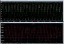
To answer the ask of Richard Marsh about the phase behavior in the VAS of a voltage/current applied at the output, like a speaker do, this will show-it all in one.
We have a 1000Hz signal in input, witch produce +-10V peak to peak in output. Let set a 1100 Hz generator (to see the phase variation) in the load, 10V in serial with the 8 ohms resistance.
The resultant signal in output is in green. We can see the damping factor of the amp has quasi nulled the EMF and CEMF, and the signal is near perfect.
In red, what we can see at the VAS input in the same time.
This illustrate how the feedback fight against EMF and CEMF and how the signal inside the loop is modified by a real loudspeaker load VS a pure resistive load.
A multi-way speaker, with all its resonances, inertias, overshoot, membrane fractioning, filters phase turns, room echoes etc... will produce inside the amp a much more complex signal than the one applied in the input.
Attachments
Last edited:
Just to recap the CFA Myths that this thread has busted
Some very definite advantages
- Noise? Simple CFAs are quieter than VFAs
- THD? Several CFAs presented here rival more complex VFAs
- PSR? Better or no worse as Christophe shows. This myth is caused by symmetrical topologies NOT by CFAs.
- For simple amplifiers, CFAs are better on ALL the usual performance parameters at equal or less complexity
- Easy zillion V/us slew
Isn't it funny how you complain about people always running into the CFA vs. VFA debate, only to get yourself into the same, a few posts later? Anyways:
- It would be interesting to find out how you concluded that simple CFAs are always less noisy that VFAs. Obviously, a CFA can be less noisy than a VFA (in particular if the VFA input stage degeneration is very large) but otherwise simple theory shows this is in general wrong, and here is why.
In a multi stage gain chain, the noise performance (defined as the input equivalent noise) is usually set by the input stage. That's because the noise contribution of the following stages is always divided by the previous stages gain. Now, in a CFA (in particular with the much beloved diamond buffer), while the input stage contributes to the noise (Rbb, emitter resistors, etc...) the gain is simply 1. This puts the entire burden of "low noise" on the VAS/TIS. This stage has its own constraints (like running at a relatively high current of 5-10mA (hence the need for a device which is not necessary noise optimized), degeneration, etc...) which makes its noise task difficult (and most likely worse than possible a multi gain stage VFA).
- In any amplifier, the distortion performance is defined by a) the open loop distortions and b) the available loop gain, to linearize the circuit, be it in the form of local and/or global feedback. In particular for audio amplifiers, the output stage always largely (99.999%) dominates the open loop distortions (there are some fine points here, like the output stage distortions are strongly depending on the VAS output impedance, but this is not an issue in a CFA vs. VFA discussion). Now if we consider the same output stage for both a VFA and a CFA, what's left to compare is the available loop gain. The available loop gain is defined by a) the unity loop gain frequency (aka ULGF) and the compensation order (1-Miller, 2-TPC/TMC, 3-NDLF, perhaps higher orders are possible, but certainly unusual in practice), and this has nothing to do with a particular toplogy. Also, in any minimum phase system (disregarding the topology), there is no way to escape the ULGF vs. phase margin trade. Therefore, the intrinsic topology (CFA or VFA) is irrelevant for the overall distortion performance. Things like "open loop bandwidth" were demonstrated to be bed time stories by Mr. Cordell himself (among others, B. Gilbert, etc...), in the context of the Ottala debate, before I was even born.
- If you care to read the paper that JCX referenced and that I posted as an attachment you will find out that the PSRR, CMRR and the open loop gain are always inter-related, disregarding a particular amplifier topology. Hence, the PSRR performance is just another trade to make. Obviously, symmetry improves the PSRR, but then not all VFAs are symmetrical and a symmetrical CFA can be easily designed (of course, with some added complexity).
- I have still to see any non-anecdotal evidence that gazillion of V/uS have anything to do with an audio amplifier SQ. Anyways, the high slew rate is not a general property of CFAs, but of a particular configuration called "current on demand". CFAs without gazillion of V/us can be easily designed, as much as a "current on demand" property can be easily implemented in a VFA (resulting in gazillion of V/uS).
Finally, to add insult to injury, what is called in this thread "CFA" barely shares the fundamental properties of a CFA, as defined by TI, Analog, etc... in the reference papers. The fundamental property of the CFA is the ability to have the open loop gain modulated by the feedback network. In all audio CFAs that I have seen here and elsewhere, this effect is not larger than a few percent, therefore they are in fact closer to a VFA than many would like to admit. In fact, the discussion is not about CFA vs. VFA, but about the best input stage topology (like: diamond buffer vs. differential). This is obviously less sexy than the CFA buzzword, but it could certainly be the subject of some intelligent discussion.
Now have fun guys, I am over and out from this thread.
Last edited:
VFA vs CFA
Esperado, I saw on your site (http://www.esperado.fr/temp/VSSA/vssa-vs-vfa.html ) very interesting comparison of VFA and CFA amplifiers, thank you for good work.
Can you provide IMD simulations for both amplifiers?
Thank you in advance.
Esperado, I saw on your site (http://www.esperado.fr/temp/VSSA/vssa-vs-vfa.html ) very interesting comparison of VFA and CFA amplifiers, thank you for good work.
Can you provide IMD simulations for both amplifiers?
Thank you in advance.
I don't think noise is an issue in power amps for the most part - it's a non issue. Period.
The fundamental difference between CFA and VFA is that in CFA the peak input current to the TIS is set by the peak output voltage and the feedback resistor value. In a VFA the peak TIS input current is set by the LTP current.
In my e-Amp design (VFA) the peak TIS input current is 10 mA. In the nx-Amp it's 110mA.
The upshot of this is that the error signals out of the input stage in the CFA are lower than a VFA because the loop is faster. Futher, the input diamond stage, without degeneration, is far more linear than an LTP, so the overall linearity of the CFA, despite only 1 active gain stage ( versus two in a conventional VFA), is similar or better than a VFA.
The practical upshot of this is that CFA's are simpler than VFA's for similar levels of performance. If we think about a 'balanced' performance amplifier in which distortion, bandwidth, SR, PSRR etc are all considered as important, CFA topologies more than hold their own.
If the mid band distortion is in the single digit ppm level, as is the case with CFA topology designs, there is no reason to suppose that a VFA topology that achieves sub ppm distortion is any better objectively, and especially do when other elements in the signal chain exhibit distortion that is is orders of magnitude higher.
None of the statements above imply that I am pro one topology over the other.
Last edited:
The practical upshot of this is that CFA's are simpler than VFA's for similar levels of performance.
With 10 transistors front end you can make a VFA
that has lower than 1 ppm THD AND IMD in the full
audio band , try this with a CFA and post the results
when available , i wont even consider PSRR to ease
the comparison...
- Home
- Amplifiers
- Solid State
- CFA Topology Audio Amplifiers