I see, I have tried the SSA and the VSSA types a few times, but frankly the diamond input versions are far better.
I like your compensation scheme, it's like nested feedback , with at short HF loop around the OPS
Connecting the Miller capacitor to the output of the output stage and thus enclosing the output stage in the short HF loop is essentially what Cherry proposed, and is called output inclusive compensation. It has been discussed quite a bit, and it generally is vulnerable to stability problems. Transitional Miller Compensation (TMC) is the preferred compromise, where the Miller feedback is taken from the output stage but where that pick-off point is transitioned to the output of the VAS at higher frequencies to avoid the stability problem.
Note that if loading of the VAS by the Miller capacitor is a concern, the Miller capacitor can be connected to the EF output of the pre-driver. This arrangement buffers the VAS output from the Miller capacitor load while not incurring the stability problems as much from enclosing the slower output transistors in the Miller loop. Nevertheless, even in this arrangement, high-frequency stability must be considered because the Miller loop can have a high local ULGF.
Cheers,
Bob
In my experience, Cherry compensation causes the Bode-step to lift, possibly above UG. Feedback caps at drivers/vas buffers were recommended to push it back down. I think this was one of Cherry's conclusions also, that 'just' the feedback cap from OPS to VAS-in is'nt enough to get to a stable point.
Well, better print: "not always enough to...".'just' the feedback cap from OPS to VAS-in is'nt enough to get to a stable point.
In this particular example, the output devices are not the slowest, thanks to FETs, despite their parasitic gate capacitance.
The response curve with no other filters is flat with no peak, despite the very high bandwidth, and, with the zobel and ouput coils, stable with all the capacitances you can try as a load.
Notice that the low pass filter i use between the two stages of the diamond allows little square waves with no overshoot, and have an influence on the loop across the parasitic capacitance of its second stage.
I tried all other solutions i knew (thanks Bob, for your input), no better.
That, of course, you have to verify, on the bench, with the parasitic capacitances of any first build.
Last edited:
Connecting the Miller capacitor to the output of the output stage and thus enclosing the output stage in the short HF loop is essentially what Cherry proposed, and is called output inclusive compensation. It has been discussed quite a bit, and it generally is vulnerable to stability problems. Transitional Miller Compensation (TMC) is the preferred compromise, where the Miller feedback is taken from the output stage but where that pick-off point is transitioned to the output of the VAS at higher frequencies to avoid the stability problem.
Note that if loading of the VAS by the Miller capacitor is a concern, the Miller capacitor can be connected to the EF output of the pre-driver. This arrangement buffers the VAS output from the Miller capacitor load while not incurring the stability problems as much from enclosing the slower output transistors in the Miller loop. Nevertheless, even in this arrangement, high-frequency stability must be considered because the Miller loop can have a high local ULGF.
Cheers,
Bob
Hi Bob,
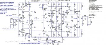
I used OIC in my CFA MOSFET power amps and all simulation show quite good stability with very good PM and even better GM.
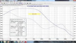
I used a kind of two pole OIC as it shows better open loop bandwidth, TMC did not behaved so good. Here is the schematic and two cases of the Loop Gain plots, as two pole OIC and pure OIC(R35 to the ground removed). I tried this approach with the VFA but it showed tendency to instability.
I would appreciate your opinion, the one I asked from D. Self was not in a favor.
Regards Damir
Attachments

Hi Esperado !
Personally I very appreciated your work & contribution in this thread !
I have read very carefully yours sims of `diamond VSSA ` amp on your home site, so I have one question for you :
You have simed behaviour (THD wise) of `diamond VSSA` amp but as I see only on steady 8 ohm load , but what will be THD let say on 2 , 4 , & 16 ohm ? ,
since as you already know many speakers with nominal 8 ohm usually have very wild impedance curves but not steady ones.
Best Regards !
Last edited:
My fault. I don't believe in THD prediction of the LTspice Pythia, and i'm lazy. In fact, i use zobels and resonnances compensation networks in my enclosures, to get a flat impedance curve (6Ohms) , as you see i didn't simulated for this value neither.since as you already know many speakers with nominal 8 ohm usually have very wild impedance curves but not steady ones
But you can download the asc file and models and play with it ?
http://www.esperado.fr/vssa-diamond/DVSSA.zip
For the same output voltage, LTSpice sims @1KHz.
16 Ohms -> 0.000487%
8 Ohms -> 0.000597%
4 Ohms -> 0.000945%
4 ohms, same power than 8: 0.001%
As the distortion ratio don't seem to change a lot with volume, you can make your mind.
But, remember, it is just simulations.
Better get an idea with the real VSSA measurements, i'm sure it will be a little better.
Esperado thanks for your efforts !
Great THD numbers for a such simple amp , I expected much much worse results as load impedance drop down , and if the real world amp. measurements show even slightly better figures than ....🙂 .
Great THD numbers for a such simple amp , I expected much much worse results as load impedance drop down , and if the real world amp. measurements show even slightly better figures than ....🙂 .
1). It doesn't take very much hack to get a giant soundstage with the CFA, which is something you'll have to fight for with the classic-miller-VFA.
2). Timbral accuracy, is an epic fight and possibly a failure mode for the CFA, but really easily done with the classic-miller-VFA (most especially at the power circuit which can be either unorthodox or expensive--your choice).
3). PRAT, such as epic forceful breeze really slammin dynamic audio is done with the CFA, and is something you'll have to fight for with the classic VFA, but actually it is quite doable with the VFA and sounds a hella lot better without problem #2.
SO, for initial satisfaction the win goes to CFA; however, for long term utility, the win goes to classic-miller-vfa for useful pleasant tone. I don't think that the news comes as a surprise. Of course we'd like to do better. The good news is that somebody did!
. . .
Given that it takes an awful lot of effort to bend/kink the laws of physics, I, personally believe that the win goes to a specific CFA--the SSA amplifier, which delivers the benefits of a CFA, but surprisingly With the pleasant useful tone of a VFA.
*
Say what ???
With all due respect Daniel, I see you use 7294 s, these are lightyears away from the sound quality one can obtain with a CFA circuit. I know because I use those 7294 s for guitar amps, I use them because they distort like hell and many guitarists like that, actually demand it, but for accurate playback they suck.
You got a schematic for that guitar amp?
I don't know what you call Timbral accuracy, but it is not possible to make a difference in the structure of an instrument in listening between the both when they are similar (same VAS, SAME OPS). Of course: They both have flat bandwidth, and CFA present a little advantage on phases at HF. A fast VFA is not a lot different from a good VFA.2). Timbral accuracy, is an epic fight and possibly a failure mode for the CFA, but really easily done with the classic-miller-VFA (most especially at the power circuit which can be either unorthodox or expensive--your choice).
At the opposite of what you said, i pretend it is in the long run CFAs can show some benefits: less listening fatigue, more ease on transients, more fluid trebles. Thanks to their 'expansive' nature.
It is not so easy to get ultra low distortion numbers with CFAs, as they don't like complex circuits by nature. But, with limited pole numbers, they can be better on this point. It is not so easy to reach a very impressive PSSR. Nothing to worry too much about or that you cannot get around.
http://www.esperado.fr/temp/VSSA/vssa-vs-vfa.html
Last edited:
'timbral accuracy'
Can someone explain what this means in Engineerish?
I would think DC to 200 kHz -0.5 dB at 10 ppm would guarantee accuracy whether is CFA or VFA.
Or am I missing something here?
😕
Can someone explain what this means in Engineerish?
I would think DC to 200 kHz -0.5 dB at 10 ppm would guarantee accuracy whether is CFA or VFA.
Or am I missing something here?
😕
Last edited:
Probably another word for PRAT, or in engi terms, time-alignment / phase over the full audio band. Directly related to transient capability.
Sounds like nonsense to me.
When LTspice closed loop responses look neat and flat, as well as phase, I tend to agree with you 😉 Though time-alignment is a real thing when it comes to multiway speakers.
Edit: Was it you that a few years ago talked about sine waves with squares imposed as a test signal? I forgot who it was, either you or Bigun 🙂
Last edited:
I have now created my "ultimate" VFA that I would prototype as is. But I'm a little jealous at the one thing I find distinctly better about CFAs, which is better phase behaviour at HF.
PM/GM is pretty tight on my VFA, but due to some specific additions, the actual stability is better than PM/GM suggests.
I now want to give a CFA front-end a good try on my VAS/OPS and see if I can get similar THD numbers, though with better PM/GM at HF over the VFA 🙂
Fun detail: Spartacus (as I've dubbed the amp) can do 1KW 20K at sub ppm bridged (crazy no?). But more interesting is, that when using electrical simulations of a speaker as load, the THD only goes up by a factor of 3, staying below 0.5PPM still.
I'll use this- and Ostrippers Slewmaster thread for useful info on CFA. Yes I'd really go dig it out 🙂
Esperado, I belivee that CFA-s can have as good PSSR numbers as any VFA, it's just a matter of making sure that gain-componets are shielded by CCS, also currents can be mirrors to the VAS stage, that will increase PSSR and also increase openloop gain and lower distortion figures.
Esperado, I belivee that CFA-s can have as good PSSR numbers as any VFA, it's just a matter of making sure that gain-componets are shielded by CCS, also currents can be mirrors to the VAS stage, that will increase PSSR and also increase openloop gain and lower distortion figures.
That is exactly how my front-end is connected to the VAS/OPS. The 'VAS' is a mere current-mirror and itself does not provide gain. (equal mirror resistors). The gain-element part of the VAS is wat drives the mirrors with a differential current in such way that each leg facilitates "current-on-demand", though limited by a "window clamp" at the VAS input.
Edit: As for PSRR, I'm always using a regulated front-end supply, which already should help a great deal in getting rid of power noise. It'll give more leeway for CFAs too I think.
Last edited:
'timbral accuracy'
Can someone explain what this means in Engineerish?
May be the overloaded source due to lowish input impedance?
- Home
- Amplifiers
- Solid State
- CFA Topology Audio Amplifiers