P.S.: I have once almost destroyed a Cello amplifier (bridge) by a stupid square wave test. Cross conduction current.
I've seen some class-AB designs that had wonderfully pristine full-load square shape, with no crossover blip. How? Cross-conduction caused by fast signals!
And this brings up something about VAS stages which can operate in class AB, or as I've heard it called "current on-demand". I like to call this "indefinite drive" because there is no straightforward limit to the drive current.
The problem with these VAS stages is that once they are out of the push-pull region, you begin pumping DC current through the bias regulator (VAS acting like a rectifier), raising bias voltage. In some topologies this effect is bad enough to boost the output stage deep into class A on fast pulses.
On most amps the bias generator is decoupled with a capacitor, so if it's large enough the bias will only slowly ramp up. With a Vbe multiplier bias generator, bias will be much better controlled because of the exponential conductance (unless base impedance is high). But if it's a resistor, it will be more susceptible to this problem.
Amps like this should have a very good filter at the input to prevent this from happening in case there is an RFI problem at the input. Otherwise, the output stage may go into class A and burn.
If you're assessing step response for SONIC reasons, then using a large square wave signal is pointless and counterproductive anyway - it will stress the internals of the amp far beyond audio, so the results of this test can only weakly correlate with SQ in my understanding.
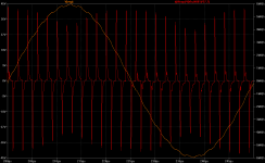
I think small-signal square wave testing is a better bet if you're looking for something to associate with sound quality. Better yet, measure step response at multiple output levels. I like to test using a max-power sine wave, with a small square wave "riding" on it. You'll see the edges of the square change shape with output level. Do a highpass or d(Vout) filter on this and you'll see all the terrible details.
Attached is one such test in simulation. I think many designers would find they have a LOT more to do, and be very busy, if they used this test on all their designs. It is one of the few tests which will dramatically increase the time you spend perfecting a design.
Attachments
Last edited:
Well, if you are looking at visual graphs, there will always be a subjective element. So much of our work is based on charts, it can be easy to do something like "smooth lines here means good amp". But there are straightforward flaws we can look for.
1: There should be no ringing, wiggles, cusps, etc. These indicate potential instability.
2: The step should have the same shape each time. This is not absolutely necessary, as long as #1 is satisfied, but any variance is a modulation of FR with output, which I think would be considered phase distortion.
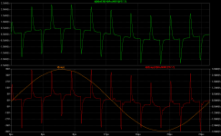
Here is another picture with an "idealized" trace for comparison. Green trace is ideal. "Ideal" may actually vary with the style of compensation or type of filtering you use, but the main thing is that it doesn't change with output level and any abnormalities are not resonances, but actually effects of the FR contour.
1: There should be no ringing, wiggles, cusps, etc. These indicate potential instability.
2: The step should have the same shape each time. This is not absolutely necessary, as long as #1 is satisfied, but any variance is a modulation of FR with output, which I think would be considered phase distortion.
Here is another picture with an "idealized" trace for comparison. Green trace is ideal. "Ideal" may actually vary with the style of compensation or type of filtering you use, but the main thing is that it doesn't change with output level and any abnormalities are not resonances, but actually effects of the FR contour.
Attachments
Last edited:
My view is different from Keantoken's.
I should make it clear I don't see the cross-conduction as a good thing. I just wanted to explain that an unusually good square wave shape can be because of cross-conduction, which is rarely a good thing.
That's at 1KHz, so you can't really see the details of the step response anyway. My last image was generated with a sine of 40KHz with a 200KHz square wave.
PS, I didn't design the amp I generated the graphs from, it was just a better demonstration because I do better than that.
PS, I didn't design the amp I generated the graphs from, it was just a better demonstration because I do better than that.
Sorry, being a little stupid here.
Trying to understand the syntax of the d(Vout) term in Keantoken's example. This is for differentiation, I think. The Vin and Vout I understand. The 27.7 is the amplifier gain? What is the other Nxx term for?
Cheers
Paul
Trying to understand the syntax of the d(Vout) term in Keantoken's example. This is for differentiation, I think. The Vin and Vout I understand. The 27.7 is the amplifier gain? What is the other Nxx term for?
Cheers
Paul
I suspect that with stimulus that high in freq you will get waveform distortion - and especially on more conventionally comp'd designs.
The two tone test simply uses the lower freq high signal level to exercise the device parameters over the full operating voltage, while the high freq small signal source checks for loop stability.
This test was first proposed in the 60's (I forget the guys name) and seems to have had a resurgence over the last few years in audio. I think Bob mentions it in his book.
Anyway, a damn good test in my view!
Sorry, being a little stupid here.
Trying to understand the syntax of the d(Vout) term in Keantoken's example. This is for differentiation, I think. The Vin and Vout I understand. The 27.7 is the amplifier gain? What is the other Nxx term for?
Cheers
Paul
d(Vout) is the dV/dT of Vout. V(Vin,n001) is the sine source minus the square source so I can isolate the square waveform out of the amp.
I suspect that with stimulus that high in freq you will get waveform distortion - and especially on more conventionally comp'd designs.
The amp uses plain Miller comp and was stressed, but not overloaded.
The frequency of either signal does not matter much - it's the impulse caused by the square wave that's being measured. That will be mostly the same regardless of the sine frequency, as long as the amp isn't near overload.
Admittedly, this is about as extreme as you could consider "small signal", but I chose these frequencies so it would present well in the graph. I've found 200KHz is a convenient square frequency on the bench and in the simulator, but usually I have the sine at 20KHz or below.
d(Vout) is the dV/dT of Vout. V(Vin,n001) is the sine source minus the square source so I can isolate the square waveform out of the amp.
Ah, it all makes sense now.
Thank you.
The square edge itself can hold many aberrations without them being visible. That's why I use d(Vout) or a highpass filter.
Doing this may allow you to see all of the rail resonances and whether your compensation is successful or not. It's extremely useful for making your amp inert, in real life and in simulation. It does take some skill to know what causes each aberration though, if there are multiple.
Doing this may allow you to see all of the rail resonances and whether your compensation is successful or not. It's extremely useful for making your amp inert, in real life and in simulation. It does take some skill to know what causes each aberration though, if there are multiple.
Last edited:
There is a name for that catagory of test: "Smoke Testing" of equipment
If this test puts the amp in any danger, then you're driving the amp too hard to observe small-step response. For this test we are looking for the step response that applies to normal audio signals.
Ugly
Well I think I have some work to do.
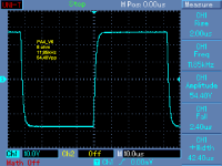
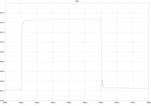
The amp clips at 51V. At lower levels the behaviour is almost ideal. It only fails close to clipping.
Keantoken, thank you for this wonderful test. (Which hopefully I have performed correctly.)
Edit: With input filter enabled. Problem disappears.
Well I think I have some work to do.
The amp clips at 51V. At lower levels the behaviour is almost ideal. It only fails close to clipping.
Keantoken, thank you for this wonderful test. (Which hopefully I have performed correctly.)
Edit: With input filter enabled. Problem disappears.
Attachments

Last edited:
It was Great Guru Baxandall. Surprise, surprise.I suspect that with stimulus that high in freq you will get waveform distortion - and especially on more conventionally comp'd designs.
The two tone test simply uses the lower freq high signal level to exercise the device parameters over the full operating voltage, while the high freq small signal source checks for loop stability.
This test was first proposed in the 60's (I forget the guys name) and seems to have had a resurgence over the last few years in audio. I think Bob mentions it in his book.
I'm not sure that 40kHz + 200kHz are appropriate. It was devised NOT produce smoke. IRRC, he used 1kHz & 20kHz.
One could consider 'real life' testing with supersonic signals in the same category as striving for 1ppzillion THD and zillion V/us slew with the added frisson of the release of the Holy Smoke.
Current clipping, especially current protection circuit activation sounds worse than 'standard' well controlled voltage clipping.
Regarding AES findings, it seems that to them everything is inaudible. Lossy compression is inaudible, dynamic compression is inaudible .... how do they test it? 😉 Are they connected with mass production business to support trends?
It's like any other periodical. Just check their list of sponsors.😱
- Home
- Amplifiers
- Solid State
- CFA Topology Audio Amplifiers