Noise. Look at the noise gain of an inverting summer with 6 channels.I have no idea why Burwen, and then Cello, used a positive or non-inverting summing topology.
Look at the noise gain of a unity gain buffer.
Look at the noise if your summer is a TL072...
I suspect Cello just re-engineered what Burwen had done, without asking topology questions.
Me, I'd have used LC and a simple single gain stage EQ, plus input buffer/inverter.
Thor
Why would you think of using a TL072 as a summer?
I would not. Mind you 5532 is not such a better choice, high current noise.
Thor
We both know that both voltage and current noise are important. The optimum circuit impedance for minimum noise factor for any opamp is Vn/In, which is why the NE5534 is such a perfect match to MM cartridge inputs.
But generally at low circuit impedances, the voltage noise dominates, and at high circuit impedances the current noise dominates (plus the Johnson noise of the resistors).
There are many other and much more recent kids on the opamp block, such as the OPA828(single) or OPA2828(dual) with 4nV/rootHz, 1.2fA/rootHz and a 1/f corner of around 20Hz. About 6-7 times the price of the NE5532AN, but knocks the 5532 spec back into the 80's.
Craig
We both know that both voltage and current noise are important. The optimum circuit impedance for minimum noise factor for any opamp is Vn/In, which is why the NE5534 is such a perfect match to MM cartridge inputs.
It's not a good match actually. NJW2068 has lower noise and lower input Bias current. Most low noise J-Fet (and very recent CMOS) Op-Amp's have lower noise as well.
The OPA1679 gives you a quad that kills 5534/32 and TL072 dead, at 56 cents for a Quad in 1kU at mouser. The OPA1679 is actually a resymbolised (read relabeled) OPA1654 with reduced testing and relaxed limits on some parameters that are not relevant to audio.
Thor
The OPA210 beats the old NE5534A for MM. Bipolar, lower voltage noise, the same current noise, and much better 1/f performance and orders of magnitude lower distortion.
But as far as noise reduction as compared to the N5534A, we are talking a hardly anything. The OPA210 results in 1.6dB as compared with a noiseless amp (with RIAA, and typical MM impedance at the input). The NE5534A gives 2.3dB as compared with a noiseless amp.
So you have gained a mere 0.7dB in SNR.
Sure you have gained a bit in headroom, much lower distortion, and much better 1/f (my spreadsheet does not handle 1/f. Yet). But noise for MM, hardly any difference.
Sure you can go discrete, but the same arguments apply.
We have kind of diverted from the various Palettes and related tone shapers.
Craig
For those who were looking into doing this with less op amps and digital control, this combo of chips seems to be still available in limited quantities and support a series RLC eq, specify low noise, but not sure if that's exactly the same topology being discussed here.
Kenwood used this combo in their GE-7030 and claim .005% distortion. (they 2 mitsubishi equalizer chips and 1 NJR electronic variable resistor chip on each channel for a 14 band per channel programmability, like the below example showing the left channel eq/amp with a JRC4558 op amp buffer. I calculated the kenwood nominal vs. circuit values for frequency and Q using the formula in the data sheet below and they are close and all have a Q of ~ 10 vs. the reference design which shows capacitors selected (C1 and C2) to give Q's of approximately 2.2, so the coonstant Q in addition to the frequency, is adjustable by selecting appropriate cap values.
New Japan radio co NJU7305
14 channel variable resistor (looks like 2db steps +/- 12db)
Design doc recommends jfet input op amps
takes 8 bit data string to program the EVRs
Look like reasonably low noise, but I'm not well versed in these things. Data sheets attached.

Mitsubishi MN5229P
7 band EQ

Kenwood values vs. nominal... You can see that a few are off


Kenwood used this combo in their GE-7030 and claim .005% distortion. (they 2 mitsubishi equalizer chips and 1 NJR electronic variable resistor chip on each channel for a 14 band per channel programmability, like the below example showing the left channel eq/amp with a JRC4558 op amp buffer. I calculated the kenwood nominal vs. circuit values for frequency and Q using the formula in the data sheet below and they are close and all have a Q of ~ 10 vs. the reference design which shows capacitors selected (C1 and C2) to give Q's of approximately 2.2, so the coonstant Q in addition to the frequency, is adjustable by selecting appropriate cap values.
New Japan radio co NJU7305
14 channel variable resistor (looks like 2db steps +/- 12db)
Design doc recommends jfet input op amps
takes 8 bit data string to program the EVRs
Look like reasonably low noise, but I'm not well versed in these things. Data sheets attached.
Mitsubishi MN5229P
7 band EQ
Kenwood values vs. nominal... You can see that a few are off
Attachments
For those who were looking into doing this with less op amps and digital control
Are probably best of loading up a suitable EQ App on their digital source. I actually figured out a way to make a Pro-Audio Digital EQ behave pretty much like the Palette back in the 90's or very early 00's.
The IC's you propose are decidedly low end performance, next to a 5532 and not suited for a Palette type EQ at all.
The biggest issue I see here is that too many look at some form of technical solutions without understanding what the "Palette" is, how it differs from any other EQ and why.
Thor

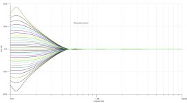
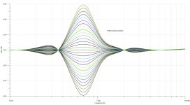
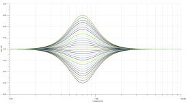
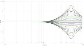
That was excellent! Any chance of any more families of curves?let's try this - 4 of 6
Craig
OK Craig,
Here are the last two.
PLUS, During my time farting around with the Palette's, I happened upon some parts and was able to build up my own version of the Levinson LNP-2. That is the one piece of "Hi Fi" equipment that I would LOVE to own, BUT prices have always and will continue to be deservedly insane. The -2 includes a 3-band equalizer that I simplified down to it's bare essentials. NOT my design. It does the trick very nicely however and turns out to include the three frequencies I absolutely use the most with other more elaborate designs/units.
Attachments

Those curves are very interesting indeed!
The very original LNP-2 used Dick Burwen's modules (UM201 for I/O and filters) and VU306 for the VU meters
https://www.burwenaudio.com/BURWEN_LABORATORIES_MP202_UM201_VU306.pdf
Levinson later replace them with ones with their own name label. No idea whether these were re-engineered, or just brand labelled Burwen ones. But the LNP-2 is indeed a thing of glorious beauty.
One of the best systems I ever heard was when Meridian in the UK were also importers of Levinson stuff. This was at the Heathrow audio show.
Meridian CD player, into a two chassis ML pre with two power supplies, into two ML Class A monster monoblock poweramps, and into two pairs of stacked Quad ESL63's. This was in the days that ML made stuff with cryptic number codes.
They put on Dire Straits Brothers in Arms - something I thought I knew pretty well. It was so astonishing glorious it was impossible to reconcile it with my system (at that time). It was like a totally different piece of music. They must have though I was bonkers - I actually started laughing.
And that, then and there in 1987 (or thereabouts), was the start of the audio rabbit hole.
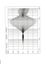
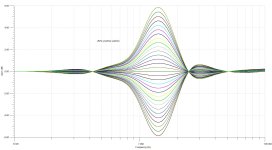
The detail in the original Cello frequency plots was fascinating.
So I put the four band Burwen version, on which the Audio Palette was based, into spice. These show exactly the same detail as the Cello ones.
The interesting thing is that the drive method into the positive summing node is totally different between the Burwen and Colangelo/Jason implementation. The Burwen drives the summer from opamps, so they are being driven by a voltage source. Whereas the Cello version is being driven by a current source (from a discrete transconductance amp, OTA-1)). But the net effect in terms of the filter shape, and out-of-band artefacts is the same whether it is driven by a voltage or a current source.
Attachments

OTA-1 is not a pure current source. The collector impedance of a transistor is given by the Early voltage divided by the collector current. I've measured some similar TO5 transistors and the Early voltage is around 600 to 1000V. The output transistors in OTA-1 run at about 20mA, so the collector impedance per transistor is 1000/20x10^-3, or 50k ohms. Both transistors are essentially in ac parallel, so the output impedance of OTA-1 is around 25k ohms. Could be lower or higher, but whatever it is not an ideal infinite value.
That begs the question: suppose one OTA-1 filter is set to provide a boost in one of the 6 frequency bands. And to do so it has to drive current in the summing node on a FET input of OTA-2. That current has to go somewhere, and the only place it can go is (a) into the 25k ohm outputs of the remaining 5 OTA-1's, or (b) through the remaining filters backwards and in into the output of the voltage follower. I suspect that both mechanisms are in play. But whatever happens the current has to go somewhere!
That begs the question: suppose one OTA-1 filter is set to provide a boost in one of the 6 frequency bands. And to do so it has to drive current in the summing node on a FET input of OTA-2. That current has to go somewhere, and the only place it can go is (a) into the 25k ohm outputs of the remaining 5 OTA-1's, or (b) through the remaining filters backwards and in into the output of the voltage follower. I suspect that both mechanisms are in play. But whatever happens the current has to go somewhere!
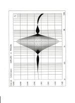
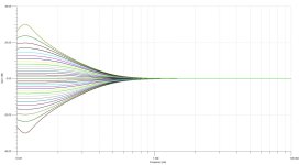
So for comparison, this is the four band Burwen filters using an inverting summer. Note there are no out of band artefacts that are characteristic of a positive summer.
Attachments

However, as previously noted up this page, there is a noise penalty to a negative summer. For comparison, here is the output noise and SNR of three different opamps in the inverting and non-inverting summers. Spice of course. and noise calculated on a 20Hz to 20kHz bandwidth.
NE5532A. Positive summer, 3.4uV, 109dB (Burwen's choice of opamp)
NE5534A. Negative summer, 10.1uV, 100dB
OPA827. Positive summer, 2.5uV, 112dB (JFET)
OPA827. Negative summer. 6.7uV, 104dB
OPA1612. Positive summer, 1.7uV, 115dB (current generation of low noise bipolar)
OPA1612. Negative summer, 4.4uV, 107dB
The difference between the two is not small - typically 8-9dB. Sure you get smooth curves which is nice. But the noise penalty is significant
Using the 1.1nV/rootHz OPA1612 gives spectacular low noise in the positive 4-band Burwen. 115dB SNR is very quiet indeed.
That seems to be the reason that Burwen and then Cello's version chose the positive summer, and just accepted the non-ideal filter shapes.
Craig,
Their work was done over/around 40 years ago. How sophisticated might they have been with op amp design at the time? What modeling programs were available then?
Their work was done over/around 40 years ago. How sophisticated might they have been with op amp design at the time? What modeling programs were available then?
OrCAD was available back in '85, as command line spice editor. As tricky to use as the corresponding optical design program Code-V which I was unlucky to work with at around the same time.
But great electronic designers, like Burwen, Colangelo and Jason knew enough about filter and analog design to work it out from first principles. We are really lucky that we can do what-ifs using schematic based spice analysis in seconds.
But great electronic designers, like Burwen, Colangelo and Jason knew enough about filter and analog design to work it out from first principles. We are really lucky that we can do what-ifs using schematic based spice analysis in seconds.
UC Berkeley distributed SPICE2 for free starting in 1975 -- long before the invention of personal computers. I used it myself on timeshared mainframe computers in 1978, and the circuit we designed (completely relying upon SPICE) worked beautifully. Back then you had to create (and validate!) your own .SUBCKT models but nobody complained too much -- there simply was no alternative.
The difference between the two is not small - typically 8-9dB.
If you ask me, that.....
Thor
Regarding opamps in '85, the 5532 (1979) and 5534 (1981) were streets ahead of previous opamps, so it is not surprising that Burwen used the 5532A in his prototype Audio Palette. He kept circuit impedances to be greater than 2k ohms, because he noted that distortion rises at lower impedance loads. If he needed to drive lower impedances, he doubled up the opamps to share the load.
Of course the Audio Palette implemented Burwen's design using discrete circuits. And where Burwen used servos to re-zero any DC offsets before switches and controls, the Audio Palette used capacitor coupling.
I have not done a noise analysis of the discrete Audio Palette implementation.
Of course the Audio Palette implemented Burwen's design using discrete circuits. And where Burwen used servos to re-zero any DC offsets before switches and controls, the Audio Palette used capacitor coupling.
I have not done a noise analysis of the discrete Audio Palette implementation.
- Home
- Source & Line
- Analog Line Level
- Cello Palette Style EQ Design (was High End Tone Control)...