Nope, I was one of the Founders of AMR & iFi and designed most of their products (AMR too), up to 2019. I have not had anything to do with iFi or AMR since.
Thor
Thor
Two 74HC14. One per channel. They run from a vanilla 7805 from the +28V regulated line coming in. So not much current draw at all.
I'm not sure if the 7805 has a minimum current to regulate, like the 317/337 do. There are a few searchable references that suggest 5mA is needed from a 7805 to ensure regulation, but that figure is not in the datasheets. A simple resistor of 1k or so would ensure that.
Have a look at the TI datasheet, specifically Electrical Characteristics, which specifies load regulation from 5 mA to 1.5A. I read that as no guarantee of load regulation below 5 mA.
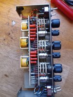
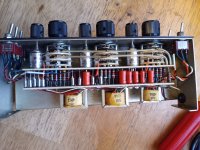

Nicely made, except for the tantalum capacitors
They are axial hermetically sealed wet tantalum, often mil spec. Seriously not cheap. And the only tantalum capacitors approved for use in space vehicles.
A very different beast indeed to the sintered bead types that everyone rightly hates, and that introduce harmonic distortion.
I would not say " everyone " since there is a number of deaf people who love Naim and are willing to spend a fortune to get that harmonically distorted sound🙂
The space approval doesn’t remove tantalum’s dielectric constant wet or dry. Wet improves surge current, not audio processing. I have all dc coupled equipment with servos and offset sensing protection. I left tantalum coupled equipment back in the 70s.
Last edited:
Dielectric constant is essential for the operation of any practical capacitor. The only exception are esoteric vacuum or inert atmosphere capacitors used in standards equipment.
I have Erno Borbely DC decoupled phono stage with servo and offset sensing. It's a nice sounding phono stage. All my cap coupled phonostages are significantly better sounding for one or another reason. I like beaded tantalum sound signature in a particular setup and I don't feel the need to defend that choice. There are plenty of people who like that signature above all other. Almost every wall flower eventually get married too🙂The space approval doesn’t remove tantalum’s dielectric constant wet or dry. Wet improves surge current, not audio processing. I have all dc coupled equipment with servos and offset sensing protection. I left tantalum coupled equipment back in the 70s.
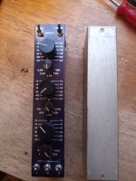
Back to the corrector , I need to figure out which of " white , red , black" cut wires is the output and input wire . Black appears to be a common ground wire. Care to make an educated guess based on experience with vintage pro audio color coding ;???)
I too have Borbely’s phono, along with his line amp and DAC. Borbely s shunt regulators, film caps are Re Cap Teflon and RTX polystyrene , ( the RIAA caps are 1% teflon). Blackgate bipolar electrolytices, TX2575 resistors and trimpots. I have other tube and solid state - phono and line stages, one has from the 70’s tantalum coupling caps, nothing I enjoy now. . Line amp and Dac with power supplies pictured
Attachments
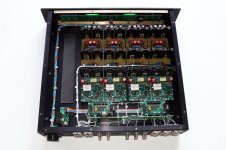
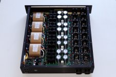
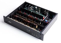
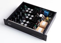
Parts sourced and boards stuffed by me, chassis and assembly by Les Bordelon. Pre regulators are Jung / Didden +/- 31 volt super regulators on custom 2x 2 inch boards Each chassis runs 25 watts Class A dissipation. Teflon/Silver wired, stepped resistor attenuator. 100 watt R-core transformer per phase. Quasimode snubbed hexfet bridges for each polarity and each phase with 240,000 uf of CRC pre filtering. Now I’m broke and tired.
Last edited:
FWIW,
As written before, I had an opportunity to "play around with" (and implement) the Palette Pre hardware along with a lot of documentation on it; the original Palette and Dick Burwen's original (op-amp-based) concept drawing. Also looked up other equalizer info, especially that in the old (1985??) National Semiconductor (NS) Audio Handbook. Something always bothered me but couldn't put a finger on it. In a lot of program equalizer designs like the NS, the individual filter sections were all put electrically in PARALLEL - with appropriate input/output buffering. BUT in Burwen's and following Cello incarnations, the sections were put in SERIES/PARALLEL! Specifically, the 15hz; 500hz; 2K and 25Khz sections were in PARALLEL, followed by another paralleled 120hz; 5Khz section in SERIES with the first. Never had nor taken the chance to ask either of the few remaining original individuals if they remember why this was done.
There are certainly good electrical reasons why they should all be in parallel, like maybe lower noise/distortion. But do realize now that with this all paralleled approach, any boost or cut in any one frequency section is passed thru (unaltered) to the other frequency sections and then added together. Whereas in the parallel/series approach, there can be more of an amplitude interaction between the two paralleled sections AND any "corrections" in the later (120hz, 5Khz) filter sections will have more amplitude effect than in the all paralleled approach. Any thoughts? At least it's not keeping me up at night anymore.
Do have in front of me the original Palette's Audio Precision plots - dB vs frequency - for the each band's control switches Will try to copy and post them
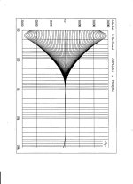
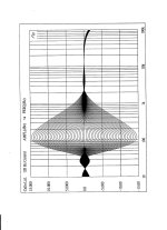
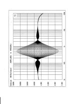
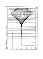
Spice simulation of Burwen's original op-amped prototype of the Palette gives the same behaviour with the ripples outside the nominal filter profile. This is a result of using a positive summer - the filter outputs go into the positive input of an opamp - semiconductor in Burwen and discrete in the Palette.
If a negative summer is used, as per my posts an eternity ago, those artefacts disappear and the filter profiles are clean.
I have no idea why Burwen, and then Cello, used a positive or non-inverting summing topology. They are a real fight to design and make the filter profiles independent, so turning two profiles up might not produce an independent sum.
- Home
- Source & Line
- Analog Line Level
- Cello Palette Style EQ Design (was High End Tone Control)...