A handy hint regarding woofers this old >
As can be seen in the Video part 1, removing the woofer shows oxidation/corrosion on the magnet assembly.
This corrosion can easily migrate to the 'flexible chassis to cone' wires. To prevent these wires from failing,
you can very gently coat the wires with engine oil using a 'baby art brush'. WD40 & the like is too thin.
PS.
In the Video part 2, I noticed a couple of things said and a drawing > One interesting, the other incorrect :
He said that he has found BP electrolytics to sound less 'harsh' than Polly's.
I too have found this to be true (driver dependent) but never stated it due to the barrage of critics out there.
Throughout the video, he refers to the Mid & Hi level adjustments as "L-pads" but draws a potentiometer
stating that it maintains constant impedance to the XO.
Pot's and L-pads are not the same thing 😉
@Mister Audio. What is this epidemic of "Winking" going on in this forum? Always a Red Flag to me. Say what you mean!
You are about to get both barrels from me.
Pots and L-Pads ARE the same thing.

But you are half right in that a potentiometer can never be constant impedance, unless the load is high impedance.
For that you need a stepped attenuator, here in the amplifier version:

All very tricky. But in fairness to Matt Haycross ( Who I think was trying to keep it simple for stupid, aka KISS...), even Celestion made this schoolboy mistake in the 551 brochure:

I have great confidence in Matt Haycross. Spent 3 hours last night watching some of his videos. Very experienced. Not only does he repair very broken speakers, but is now designing BBC style monitors.
And he certainly won me over with his latest interest based on the Rogers C33. This is my sort of speaker, the one I want as a stereo pair:

Everything I like in a speaker. 😉
You are about to get both barrels from me.
Throughout the video, he refers to the Mid & Hi level adjustments as "L-pads" but draws a potentiometer
stating that it maintains constant impedance to the XO.
Pot's and L-pads are not the same thing 😉
Pots and L-Pads ARE the same thing.
But you are half right in that a potentiometer can never be constant impedance, unless the load is high impedance.
For that you need a stepped attenuator, here in the amplifier version:
All very tricky. But in fairness to Matt Haycross ( Who I think was trying to keep it simple for stupid, aka KISS...), even Celestion made this schoolboy mistake in the 551 brochure:
I have great confidence in Matt Haycross. Spent 3 hours last night watching some of his videos. Very experienced. Not only does he repair very broken speakers, but is now designing BBC style monitors.
And he certainly won me over with his latest interest based on the Rogers C33. This is my sort of speaker, the one I want as a stereo pair:
Everything I like in a speaker. 😉
Last edited:

Pot's and L-pads are not the same thing
I know that you know how an L-pad works as you have explained it in the past (see post #24):
https://www.diyaudio.com/community/threads/crossovers-l-pads.401553/page-2#post-7410046
I would say that an L-pad is a form of potential divider that maintains a constant impedance for the crossover by varying a series resistance inversely with a parallel resistance.
I would say that an L-pad is a form of potential divider that maintains a constant impedance for the crossover by varying a series resistance inversely with a parallel resistance.
And you'd be wrong, @Galu the Googler! 🙂
Parts Express are equally mistaken:
https://www.parts-express.com/L-Pad-50W-Mono-1-Shaft-8-Ohm-260-255?quantity=1
Just set up the circuit diagram with, say, an 8 ohm or a 4 ohm load and assume the pot is 8 ohms and load impedance varies between 2.7 ohms and 8 ohms depending on the position of the wiper!
The only thing you CAN do, is maintain a constant source impedance with a zero ohm feedback amplifier with the circuit you quote.
@Turbowatch2. Yes, I know what an MTM or D'Appolito speaker is, and how it works with BW3 slopes. Matt Haycross added a particularly interesting extra feature which had never occurred to me. 😎
Last edited:
Just set up the circuit diagram with, say, an 8 ohm or a 4 ohm load and assume the pot is 8 ohms and load impedance varies between 2.7 ohms and 8 ohms depending on the position of the wiper!
I don't know what you mean by "assume the pot is 8 ohms".
A potentiometer has one resistive winding, whereas an L-pad has two resistive windings, as shown below (courtesy of Perry Babin).
In an L-pad, the series resistance will vary from 8 Ω maximum to zero Ω, while the parallel resistance will vary from zero Ω to 120 Ω and then infinity at full clockwise rotation.
What is this epidemic of "Winking" going on in this forum? Always a Red Flag to me.
Everything I like in a speaker. 😉
@Mister Audio. I was being IRONIC.... 😉
Mister Audio and @Galu. I am starting to think that you are right and I am wrong here on this L-Pad business. 😳
https://willys-hifi.com/collections/l-pad-attenuators
But I need to think about this and read the literature. It may explain the trouble I had reverse-engineering the famous WLM La Scala loudspeaker:


https://6moons.com/audioreviews/wlm5/lascala_2.html
All my sims went wrong when I was assuming that was a potentiometer. See the La Scala uses Visaton drivers, so simming them ought to have been easy for me. 🙁
Mister Audio and @Galu. I am starting to think that you are right and I am wrong here on this L-Pad business. 😳
https://willys-hifi.com/collections/l-pad-attenuators
But I need to think about this and read the literature. It may explain the trouble I had reverse-engineering the famous WLM La Scala loudspeaker:
https://6moons.com/audioreviews/wlm5/lascala_2.html
All my sims went wrong when I was assuming that was a potentiometer. See the La Scala uses Visaton drivers, so simming them ought to have been easy for me. 🙁
@Galu. I am starting to think that you are right and I am wrong here on this L-Pad business. 😳
The low resistance leg is 8 Ω while the high resistance leg is typically 120 Ω or could be even higher as shown below:
In the volume full DOWN position, the 8 Ω low resistance is in parallel with the input, and the tweeter is shorted to ground by the high resistance leg.
In the volume full UP position, the 8 Ω low resistance is out of the circuit, and the 600 Ω high resistance is in parallel with the tweeter.
@Galu. I can't get it to work!
Consider mid position on the wiper.
Comes out as 4 ohms from Rp1 plus 8 ohms from the load making 12 ohms plus a tiny parallel 300 ohm reduction from 600 ohm Rp2!
Whatever I do, I only get 8 ohms from 2 out of the three positions. I mean, it's either constant or it isn't!
Even Rp2 at 16 ohms overall then goes wrong in the top wiper position.
Obviously gets quite close, but not exactly constant! 🙁
Last edited:
Let's take the parallel resistance to be the typical 120 Ω.
If we assume that Rs = 4 Ω corresponds with Rp = 60 Ω then load resistance is 7 Ω (60//8) + 4 Ω = 11 Ω.
However, what if the above 'half one, half the other' type correspondence does not hold?
Perry Babin gives the following figures for an 8 Ω; 120 Ω variable L-pad. See section 122, L-pads: https://www.bcae1.com/
Fully attenuated: Rs = 8 Ω, Rp = 0 Ω, Rp and driver in parallel = 0 Ω, load presented to amplifier = 8 Ω
2.5 dB attenuation: Rs = 2 Ω, Rp = 24 Ω, Rp and driver in parallel = 6 Ω, load presented to amplifier = 8 Ω
Note that, although the max Rs of 8 Ω has been divided by four in the 2.5 dB attenuation case, the max Rp of 120 Ω has not.
There may be more to this than meets the eye!
That's a nifty compact crossover > but note the steel back of the 'level adjustment devise' will change the inductor value.
Quite right, but surely you'd just adjust the coil value to compensate?
But it is UGLY and amateurish looking. In fact I don't believe this VERY sloppy looking crossover is what is inside a 2,000 Euro loudspeaker.
I think WLM were guarding their secrets with this smokescreen. 😆
What interested me is that you can build a good loudspeaker from such cheap components.
So I did:

I prefer the Monacor cone tweeter to the Visaton one. And I did a much more sophisticated crossover.
But it is UGLY and amateurish looking. In fact I don't believe this VERY sloppy looking crossover is what is inside a 2,000 Euro loudspeaker.
I think WLM were guarding their secrets with this smokescreen. 😆
What interested me is that you can build a good loudspeaker from such cheap components.
So I did:
I prefer the Monacor cone tweeter to the Visaton one. And I did a much more sophisticated crossover.
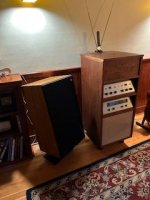
I find the bass to be really satisfying with my pair of Ditton 551. Their fibre cone woofers need plenty of power to get up and go. I wouldn’t think a tube amp would be a good match. I use a Sansui AU-555A as a preamp into an XTZ Edge A2-300 which powers the Celestions.

Beatiful looking speakers Hides!
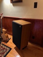
Since recap I notice my speakers seem more "stable".
I am glad I did it as there were other connection issues that got addressed.
No fun taking out those drivers.
The Bass seems very dependant on the source recording.
If I go up to about 3 on the Fisher KX-200 they are pretty damn loud in my small room.
(Wife must be out!)
Next need to build some original looking stands!
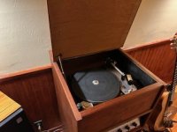
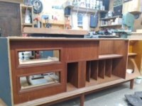
Pics of Fisher project that started the search for nicer speakers.
I had to shrink teak cabinet.
Original cab was almost 8' long!
Since recap I notice my speakers seem more "stable".
I am glad I did it as there were other connection issues that got addressed.
No fun taking out those drivers.
The Bass seems very dependant on the source recording.
If I go up to about 3 on the Fisher KX-200 they are pretty damn loud in my small room.
(Wife must be out!)
Next need to build some original looking stands!
Pics of Fisher project that started the search for nicer speakers.
I had to shrink teak cabinet.
Original cab was almost 8' long!
Attachments
Hey there Glowin - looking good! My wife is the same. Unless it’s Taylor Swift, then it can be loud.
- Home
- Loudspeakers
- Multi-Way
- Celestion Ditton 551