to reddish
Hi Chris,
there are several problems with your current situation.
I have added ---> (numbers) in the Quote Box above for the points I will reply to below:
(1) 10R is too low. It needs to be 15R with SEAS H737/19TFF1 ... if you want to use 1R in Series for an L-pad there.
Use a 4 watt or higher for the 1R, and a 9 watt or higher for the 15R, and both in wirewound.
I recommend you buy two of 0.5R in 4 watt at same time if you are buying via Mail Order, so that you can increase tweeter output a little if 1R makes it too quiet,
and 27R in 9 watt or 10 watt to replace the 15R in case you want to go to full output of the tweeter.
(2) please post the Name of that "site", or a Link to it, so that I can read their reason for recommending 10R with that SEAS tweeter.
(3) MKT will sound a bit muddy compared to MKP caps,
and electros in the bass will cause hangover of signal and delayed release of part as result of Dielectric Absorption {DA}, thus muddying the new incoming signal.
Remember, the bass driver is reproducing the low-midrange signal also for Ditton 44 and 66, thus the electros' characteristic sound is audible for about forty percent of the frequency spectrum.
MKTs have about 10 times as much DA as MKPs, and electros have very much larger DA.
I recommend you change the Jantzen MKTs to Jantzen Cross Caps or ClarityCap PX series at least, for the mids and treble filters,
and change the electros to Cross Caps or Axon or Solen in the bass filter.
{If you are buying Jantzen from "Audio Components", then buying parts is OK,
though I recommend that you do not buy any of their design services at this time because there may be a problem with those, which we are trying to sort out at this time.}
BEFORE you buy anything, look on Page 66 of this Thread, at Post #659 by moermusic.
That is the basic recommended circuit, except that for 44 there is one larger inductor and one larger capacitor in the mids' filter.
See where "moermusic" has resistors.
{You will not need the 82R, and where he has 27R is where you have your L-pad, and 2R7 will likely be better for your mids' cone than 3R3.}
If you can draw the schematic for your current circuit and Post it here, or in the:
Crossover nightmare!!!!!!!
thread, which is an ongoing Ditton 44 thread, started by:
lorienblack
I will be able to see exactly what you have, and can advise more.
(4) the cabinet has must be sealed around the tweeter,
{and sealed everywhere}
for that design to work properly, or you will have at least a bit of strange bass and lower midrange behavior audible.
Seal it in such way that there is no vibration of the seal,
and if the seal can be made for the tweeter's flange to be flush fit to the front of the baffle, there will be smoother treble.
Also, if your 44s have the recessed baffle/extended side panels, the sound can be made better by treating the extended side panels with absorptive material.
I have posted some about that in this thread {much earlier, and once recently} and I will be posting about it here again very soon
- hopefully before DennyG spends time doing test mesurements !
i replaced the tweeters with the seas recommended here with a 1r resistor in series
---> (1) and a 10r in paraell <---{'oi, spelling is "parallel", or does your fingers hit wrong keys like mine sometimes do}
---> (2) which had been listed as optimum on another site.
---> (3) I also recapped the crossover's with jantzen mkt caps for the treble and mid and electro's for the bass, but now the sound i lifeless with no detail and the soundstage is very closed in.
---> (4) Also i should mention that the cabinet around the tweeter is no yet properly sealed due to christmas post.
I am after any advise with this, could the resistors be the wrong value, could it be a lack of esr simulating resistors or is it the mkt caps that just ar'nt very good.
thanks
chris
Hi Chris,
there are several problems with your current situation.
I have added ---> (numbers) in the Quote Box above for the points I will reply to below:
(1) 10R is too low. It needs to be 15R with SEAS H737/19TFF1 ... if you want to use 1R in Series for an L-pad there.
Use a 4 watt or higher for the 1R, and a 9 watt or higher for the 15R, and both in wirewound.
I recommend you buy two of 0.5R in 4 watt at same time if you are buying via Mail Order, so that you can increase tweeter output a little if 1R makes it too quiet,
and 27R in 9 watt or 10 watt to replace the 15R in case you want to go to full output of the tweeter.
(2) please post the Name of that "site", or a Link to it, so that I can read their reason for recommending 10R with that SEAS tweeter.
(3) MKT will sound a bit muddy compared to MKP caps,
and electros in the bass will cause hangover of signal and delayed release of part as result of Dielectric Absorption {DA}, thus muddying the new incoming signal.
Remember, the bass driver is reproducing the low-midrange signal also for Ditton 44 and 66, thus the electros' characteristic sound is audible for about forty percent of the frequency spectrum.
MKTs have about 10 times as much DA as MKPs, and electros have very much larger DA.
I recommend you change the Jantzen MKTs to Jantzen Cross Caps or ClarityCap PX series at least, for the mids and treble filters,
and change the electros to Cross Caps or Axon or Solen in the bass filter.
{If you are buying Jantzen from "Audio Components", then buying parts is OK,
though I recommend that you do not buy any of their design services at this time because there may be a problem with those, which we are trying to sort out at this time.}
BEFORE you buy anything, look on Page 66 of this Thread, at Post #659 by moermusic.
That is the basic recommended circuit, except that for 44 there is one larger inductor and one larger capacitor in the mids' filter.
See where "moermusic" has resistors.
{You will not need the 82R, and where he has 27R is where you have your L-pad, and 2R7 will likely be better for your mids' cone than 3R3.}
If you can draw the schematic for your current circuit and Post it here, or in the:
Crossover nightmare!!!!!!!
thread, which is an ongoing Ditton 44 thread, started by:
lorienblack
I will be able to see exactly what you have, and can advise more.
(4) the cabinet has must be sealed around the tweeter,
{and sealed everywhere}
for that design to work properly, or you will have at least a bit of strange bass and lower midrange behavior audible.
Seal it in such way that there is no vibration of the seal,
and if the seal can be made for the tweeter's flange to be flush fit to the front of the baffle, there will be smoother treble.
Also, if your 44s have the recessed baffle/extended side panels, the sound can be made better by treating the extended side panels with absorptive material.
I have posted some about that in this thread {much earlier, and once recently} and I will be posting about it here again very soon
- hopefully before DennyG spends time doing test mesurements !
Last edited:
internal wiring, and an upcoming Post
Hi Denny and Wayne,
I will have to delay the post about internal wiring till I have more time available,
but for now the the Audioquest and Chord wires that each of you have used is not likely causing any problems.
Keep the old tin plated copper wire that you took out, because it is quite good for general purpose connecting wire for test circuits, etc ...
The output stages of some amplifiers are designed to work best into the particular Inductive and Capacitive and general Characteristic Impedance
of particular cable types.
This is a complex topic, and I'll not pursue it here except if relevant to the particular amplifiers you are each using to drive your l'speakers.
Denny,
I'll be posting about how to prepare the 66 cabinet's baffle panel as soon as I have time to, so that you can have measurement results with less delayed reflection interference corrupting them.
Wayne,
this will include your query a while ago about that product from Wilmslow Audio which you considered using under the top lip,
and which I hope you did not buy, because they have a more suitable product for that purpose.
Hi Denny and Wayne,
I will have to delay the post about internal wiring till I have more time available,
but for now the the Audioquest and Chord wires that each of you have used is not likely causing any problems.
Keep the old tin plated copper wire that you took out, because it is quite good for general purpose connecting wire for test circuits, etc ...
My only experience with Linn and cables was in the 1980's when I had a couple of amplifiers on trial at home. My memory is a little hazy on this but I do recall that one amp was a little Linn that was well reviewed and the sound from it was highly dependent on the speaker cable. It was not good sounding with any of the cables I had on hand. Each cable resulted in a different sound. Could it be that they want you to buy their own cable?
DG
The output stages of some amplifiers are designed to work best into the particular Inductive and Capacitive and general Characteristic Impedance
of particular cable types.
This is a complex topic, and I'll not pursue it here except if relevant to the particular amplifiers you are each using to drive your l'speakers.
Denny,
I'll be posting about how to prepare the 66 cabinet's baffle panel as soon as I have time to, so that you can have measurement results with less delayed reflection interference corrupting them.
Wayne,
this will include your query a while ago about that product from Wilmslow Audio which you considered using under the top lip,
and which I hope you did not buy, because they have a more suitable product for that purpose.
Last edited:
Alan thankyou for your replys i will read more carefully when the wife and kids are not here.
Now for a little request if i may, someone posted a technical/sale's brochure for the ditton 66, but the link is no longer avalible could anyone post it again or send it to me via e-mail.
Thanks in advance.
chris
Now for a little request if i may, someone posted a technical/sale's brochure for the ditton 66, but the link is no longer avalible could anyone post it again or send it to me via e-mail.
Thanks in advance.
chris
Hi Alan
I have been following this thread for some time and though it about time that I got on with things. I have a pair of 66s and would like to change the tweeters and upgrade the capacitors. As discussed in the thread I intend to go with the SEAS 19TFF 1 tweeter replacement and to use the Solen 250v PA capacitors, including the use of a 25uf in the mid and the 68uf/75uf combination in the bass sections.
I would very much appreciate you having a look over resistor placement in the attached diagram. I have tried to follow the advice re the ESR compensation resistors and the 82R across the MD500s in the mid-section in the thread and would just like to check whether this is pretty much current thinking, or not.
I would be very interested in hearing from others who have completed these upgrades for views the resulting sound quality compared to the originals.
Thanks in advance
Jim
Attachments
Jim: My xovers were *designed* by Alan for my decreased hearing of hi freq. I am good now with what I have. The 82r in the mids might not be required for you. the originals had no r in this position.
Having looked at your schematic brings me to ask Alan a question- maybe important, I dont know. DOES IT MATTER IF A R IN SERIES WITH A CAP IS BEFORE OR AFTER THE CAP? Mine are all before, whereas I see Jim has his after. Any difference?
Doug(moermusic)
Having looked at your schematic brings me to ask Alan a question- maybe important, I dont know. DOES IT MATTER IF A R IN SERIES WITH A CAP IS BEFORE OR AFTER THE CAP? Mine are all before, whereas I see Jim has his after. Any difference?
Doug(moermusic)
Measure this please
Before I post at length about making measurements of driver frequency response with the drivers mounted in the 66 cabinet,
please will WayneSwann, or DennyG, or anyone else interested,
measure the distance from UNDER the top lip of the 66 enclosure to:
(1) - the outer edge of the tweeter mounting flange,
(2) - the inner edge of the tweeter flange but NOT overlapping the suspension/surround material around the diameter of the tweeter's dome,
in mm, or, inches' + fractions, and post here.
***************
Hi jt954,
I will reply to your post next, and as soon as I have time available.
I see one error in your schematic.
Hi Doug,
I'm pleased that the treble and upper mids are now to your liking !
Your resistors are correctly placed - I will comment more about circuit placement when I reply to jt954.
Hi Moondog55,
thankyou for notifying us of the original mid-cones.
Those may be of more interest in a Ditton 44 thread, but are interesting regardless.
Hi Alan,
Would a strip 'Acoustic Laminate Panel' which is a 10mm acoustic foam on a 2mm bitumen backing, as supplied by 'Wilmslow Audio' do the job?
Regards
Wayne
Before I post at length about making measurements of driver frequency response with the drivers mounted in the 66 cabinet,
please will WayneSwann, or DennyG, or anyone else interested,
measure the distance from UNDER the top lip of the 66 enclosure to:
(1) - the outer edge of the tweeter mounting flange,
(2) - the inner edge of the tweeter flange but NOT overlapping the suspension/surround material around the diameter of the tweeter's dome,
in mm, or, inches' + fractions, and post here.
***************
Hi jt954,
I will reply to your post next, and as soon as I have time available.
I see one error in your schematic.
Hi Doug,
I'm pleased that the treble and upper mids are now to your liking !
Your resistors are correctly placed - I will comment more about circuit placement when I reply to jt954.
Hi Moondog55,
thankyou for notifying us of the original mid-cones.
Those may be of more interest in a Ditton 44 thread, but are interesting regardless.

Thankyou !
Hi sba,
thankyou indeed for posting with all those measurements
- various of those will be useful over time here.
Did you apply any treatment under that top protrusion before you made your measurements ?
Reflections from it will be too short in time to Gate out without losing necessary detail of lower treble frequencies,
and similarly for reflections from the mid-domes.
Reflections will come from the side-channels also, and will be noticeable, but not of the same magnitude as from the top-lip.
The 4mm protrusion of the woofer chassis will cause some interfence with mids' measurements,
but not as much as the top lip overhang and side-channels,
because the woofer flange is curved, thus most will reflect off-axis to the microphone.
Yes, there will be reflections off each of the domes of signal from the other dome,
but those will be small, and will be part of what you will be hearing when you play music,
thus we may as well see the effects of those in the plots.
It is useful to see only those, and not the other reflections, when considering modifications to the crosovers.
***
Wayne and DennyG, check to see your cabinets have the same overhang as sba's, as each of you have different models,
though likely the overhang will be the same on all, and also the side-channels, etc ...
I have to go now, but I'll return to this as soon as I have time available.
************
Hi jt954,
don't buy yet, as you'll have at least one incorrect capacitor for the SEAS tweeter,
and perhaps two depending on the type of response you want.
I'll get back to this as soon as I have time available.
Last edited:
Alan
I am now considering using the Jantzen Cross Caps as seems easier. So was thinking of the following:
Tweeter circuit - 3.9 and 6.2uf
Mid circuit - two 12uf to make the 24 and a single 3.9uf
Bass circuit - pairing 33 and 39uf for each of the 72uf needed
Alan - does that seem about right?
Doug - noted your comments re the fact that the 82R resistor is not necessary for the mid section - thanks for that.
Jim
Box dimensions / internal wiring
Hi Alan,
BOX DIMENSIONS
My box front panel dimensions look the same as those posted by sba. Will check when I get a chance and will post if they are different.
REPLACEMENT CAP VALUES
I've finally received the Sonicaps here are the measured values as requested Alan:
Nominal 4uF: 3.92, 3.95, 4.00, 4.01
Nominal 6uF: 6.15, 6.15
Nominal 24uF: 24.2, 24.2
I hoped to have these installed by now but USPS took 19 days to get them from Texas to Australia! Can't replace them for a few weeks now.
INTERNAL WIRING
I need to get longer internal cables so any comments would be welcome.
... I also want to check out other test software. Do you know what software others use, sba in particular?
Hi DennyG,
I'm just catching up with this thread. I use two different programs--
* HolmImpulse--
HOLM Acoustics
and
* RoomEQwizard--
Room EQ Wizard - REW Home Page
I've cross-tested them and they both work well. I prefer EQ wizard because of its ability to display and manipulate multiple measurements. Additionally, it will walk you through a soundcard calibration, and it can check your levels (for clipping) prior to taking a measurement.
Baffle

Hi Alan,
I agree, and it's likely that some of the problems on the baffle are masking some of the finer electrical trims being made to the crossover.
From this (ebay) photo it looks like Celestion made some improvements on the later 662 model--

I probably wont have time to experiment until this summer, but here's some modifications that I have in mind:
* cut off the top lip
* overlay a new partial baffle for just the mid & tweeter
(3/4" baltic birch, with rounded or tapered edges)
* offset the mid & tweeter
* drill some mounting holes into the flanges of the mid & tweeter
* cut down the existing metal grille to cover just the woofer & a.b.r.
A little ambitious, eh?
It would look something like this--

Hi sba,
thankyou indeed for posting with all those measurements
- various of those will be useful over time here.
Did you apply any treatment under that top protrusion before you made your measurements ?
-- NONE
Reflections from it will be too short in time to Gate out without losing necessary detail of lower treble frequencies,
and similarly for reflections from the mid-domes.
Reflections will come from the side-channels also, and will be noticeable, but not of the same magnitude as from the top-lip.
The 4mm protrusion of the woofer chassis will cause some interfence with mids' measurements,
but not as much as the top lip overhang and side-channels,
because the woofer flange is curved, thus most will reflect off-axis to the microphone.
Yes, there will be reflections off each of the domes of signal from the other dome,
but those will be small, and will be part of what you will be hearing when you play music,
thus we may as well see the effects of those in the plots.
It is useful to see only those, and not the other reflections, when considering modifications to the crosovers.
Hi Alan,
I agree, and it's likely that some of the problems on the baffle are masking some of the finer electrical trims being made to the crossover.
From this (ebay) photo it looks like Celestion made some improvements on the later 662 model--
I probably wont have time to experiment until this summer, but here's some modifications that I have in mind:
* cut off the top lip
* overlay a new partial baffle for just the mid & tweeter
(3/4" baltic birch, with rounded or tapered edges)
* offset the mid & tweeter
* drill some mounting holes into the flanges of the mid & tweeter
* cut down the existing metal grille to cover just the woofer & a.b.r.
A little ambitious, eh?
It would look something like this--
Last edited:
Speaker test software
Thanks for those links sba.
* HolmImpulse--and * RoomEQwizard--
I've cross-tested them and they both work well. I prefer EQ wizard because of its ability to display and manipulate multiple measurements. Additionally, it will walk you through a soundcard calibration, and it can check your levels (for clipping) prior to taking a measurement.
Thanks for those links sba.
jt954's schematic and tweeter section capacitors
Hi jt954, DennyG, sba,
I see several things to follow-up on, though with limited time available to day I'll likely only get one addressed, thus to start with the first request, which is jt954's:-
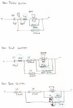
With regard to your posted schematic:
The "New Bass Section" is fine.
The "New Mid Section" is fine, though you may not need the 82R.
I advise you to listen initially with those not installed.
The 82R does three things:-
(1) - reduces Impedance magnitude of driver Fs to allow smoother low mids' crossover, and slightly less distortion caused by excess driver excursion.
The need for this varies with samples of MF and MD domes, and with some samples lower than 82R may be needed.
(2) - reduces mid-band Impedance minimum a little, which is useful if your samples are higher there than the average, and if each is different there, then a different value of resistance can be used with each to achieve a closer match between the drivers.
NOTE, I recommended to sba to apply 82R to one of his MDs only, to try to get its response closer to his other MD in both the above matters.
(3) - reduces Impedance a little in the upper mids' crossover region, which allows the .34mH inductor to drop a bit more of the upper mids if those are audibly too prominent, and from sba's plots it seems this may be more the case for the MD model domes than for the MF model domes.
NOTE, moermusic has tried this and reported some audible result.
Thus, I recommend you listen carefully for the above phenomena AFTER the new caps and other resistors are in the circuit.
Post here if anything seems audibly peculiar.
Do buy the 82R if you have to buy via Mail-order so that you have them, and resistors are not expensive,
BUT first, measure the DC resistance of each mid-dome and Post here before you order.
If each is significantly different in DCR, I may recommend a different value resistor for parallel connection to each dome.
The "New Treble Section" is not correct for the SEAS 19TFF tweeter.
I think you may have missed some posts of mine about changes to the treble section to adapt to other tweeters.
Basically, the old treble filter is suitable for the typical dome tweeter of that era which had a high Q Fs, and thus high Impedance peak at its Fs and greater output in the frequency band around and a little above the Fs region than further up the frequency spectrum.
The only current tweeter which is like those old ones, and which can be adapted to fit easily in the 66 is the Coles 4001 ... it needs only a resistor connected in parallel, and then will work with the capacitors and inductor values of the original circuit.
For the SEAS 19TFF the components will have to be changed or there will be loss of output about an octave wide centred on the crossover frequency.
By using a suitably calculated parallel resistor ONE only of the original parts can be retained, thus I calculated for the .14mH inductor, because that component does not deteriorate with age, thus will still be working well.
For the capacitors, for smoothest response through the crossover region and basically flat treble response the capacitors will need to be about 3.6uF and about 11uF.
You can use 3.9uF and 10uF, which moermusic has, but that will cause an increase in treble output a little above the 5kHz, and not as flat response above that as the alternate.
I recommended this to moermusic because of his hearing loss of upper treble,
however if you have no great loss of upper treble hearing I recommend the 3.6uF and 11uF option.
These can be made with a parallel pair of 1.8uF, and parallel pair of 5.6uF for brands with no 3.6 and 11.
Sonic Craft's Sonicap Gen I has both 3.6 and 11uF.
Some other brands have 3.6uF and 5.6uF.
You have not included a Flag with your name, thus I do not know which country you are buying from to recommend brands to buy easily,
thus where are you ?
For resistors in the treble, 1R and 15R will give similar treble level to the original, but that is slightly lower in output than the midrange output.
(see the original Celestion brochure posted by ...{ I forget who, but possibly DennyG} recently, and you will see the frequency response plot included.)
Do you want slightly reduced treble, like the original, or not quite as less, or not less but closer to midrange level ?
Hi jt954, DennyG, sba,
I see several things to follow-up on, though with limited time available to day I'll likely only get one addressed, thus to start with the first request, which is jt954's:-
With regard to your posted schematic:
The "New Bass Section" is fine.
The "New Mid Section" is fine, though you may not need the 82R.
I advise you to listen initially with those not installed.
The 82R does three things:-
(1) - reduces Impedance magnitude of driver Fs to allow smoother low mids' crossover, and slightly less distortion caused by excess driver excursion.
The need for this varies with samples of MF and MD domes, and with some samples lower than 82R may be needed.
(2) - reduces mid-band Impedance minimum a little, which is useful if your samples are higher there than the average, and if each is different there, then a different value of resistance can be used with each to achieve a closer match between the drivers.
NOTE, I recommended to sba to apply 82R to one of his MDs only, to try to get its response closer to his other MD in both the above matters.
(3) - reduces Impedance a little in the upper mids' crossover region, which allows the .34mH inductor to drop a bit more of the upper mids if those are audibly too prominent, and from sba's plots it seems this may be more the case for the MD model domes than for the MF model domes.
NOTE, moermusic has tried this and reported some audible result.
Thus, I recommend you listen carefully for the above phenomena AFTER the new caps and other resistors are in the circuit.
Post here if anything seems audibly peculiar.
Do buy the 82R if you have to buy via Mail-order so that you have them, and resistors are not expensive,
BUT first, measure the DC resistance of each mid-dome and Post here before you order.
If each is significantly different in DCR, I may recommend a different value resistor for parallel connection to each dome.
The "New Treble Section" is not correct for the SEAS 19TFF tweeter.
I think you may have missed some posts of mine about changes to the treble section to adapt to other tweeters.
Basically, the old treble filter is suitable for the typical dome tweeter of that era which had a high Q Fs, and thus high Impedance peak at its Fs and greater output in the frequency band around and a little above the Fs region than further up the frequency spectrum.
The only current tweeter which is like those old ones, and which can be adapted to fit easily in the 66 is the Coles 4001 ... it needs only a resistor connected in parallel, and then will work with the capacitors and inductor values of the original circuit.
For the SEAS 19TFF the components will have to be changed or there will be loss of output about an octave wide centred on the crossover frequency.
By using a suitably calculated parallel resistor ONE only of the original parts can be retained, thus I calculated for the .14mH inductor, because that component does not deteriorate with age, thus will still be working well.
For the capacitors, for smoothest response through the crossover region and basically flat treble response the capacitors will need to be about 3.6uF and about 11uF.
You can use 3.9uF and 10uF, which moermusic has, but that will cause an increase in treble output a little above the 5kHz, and not as flat response above that as the alternate.
I recommended this to moermusic because of his hearing loss of upper treble,
however if you have no great loss of upper treble hearing I recommend the 3.6uF and 11uF option.
These can be made with a parallel pair of 1.8uF, and parallel pair of 5.6uF for brands with no 3.6 and 11.
Sonic Craft's Sonicap Gen I has both 3.6 and 11uF.
Some other brands have 3.6uF and 5.6uF.
You have not included a Flag with your name, thus I do not know which country you are buying from to recommend brands to buy easily,
thus where are you ?
For resistors in the treble, 1R and 15R will give similar treble level to the original, but that is slightly lower in output than the midrange output.
(see the original Celestion brochure posted by ...{ I forget who, but possibly DennyG} recently, and you will see the frequency response plot included.)
Do you want slightly reduced treble, like the original, or not quite as less, or not less but closer to midrange level ?
Last edited:
Alan
I am based in the UK and think for simplicity I will stick with the Jantzen cross caps. Looks like they will need doubling up - 2x1.8uf=3.6uf and 2x5.6=11.2uf.
I guess that I would be looking for the 'not quite as less' option and see how it goes. If you could let me know the alternative resistances for your 'original' and the 'not less but closer to the midrange' options that would be helpful and I can try those depending on the initial sounding.
Thanks for your help.
Jim
Finally, 2 plots from John
Hi Alan, I hope you are well.
I have received the attached 2 plots from John, after a bit more prompting it has to be said! The email text read:
'Hi Wayne,
The plots you asked for are attached - As the original files were lost I have repeated these measurements today
Best regards
John
The second one does refer to the Celestion 66's cabinets although he said that these plots were recreated as the originals were lost?
I have attached them to this reply. I couldn't seem to be able to attach to private messages.
Best Regards
Wayne
Attachments
![SEAS_19TFF_Impedance_mag_and_phase[1].jpg](/community/data/attachments/189/189291-007db3e598bde91bf36c4cd4a74736db.jpg?hash=AH2z5Zi96R)
![SEAS_19TFF_in_Ditton_66_cabinet_1m_on_axis_anechoic[1].jpg](/community/data/attachments/189/189299-cc5b8430e995fd5468ed342c70bf899c.jpg?hash=zFuEMOmV_V)
SEAS plots
Hi Wayne,
good, and now you have something useful to work with.
The Frequency Response Data has evidence of why he put that C9+L6+R1 network in Parallel with the tweeter.
See that small peak centred at about 5.15kHz, and notice that its bandwidth is skewed to include wider band above 5.15 than below 5.15.
The C.L.R network is tuned to 5.57kHz, thus it seems intended to reduce the small plateau between 4.6kHz <--> 7kHz.
However, there is no plateau of that magnitude on SEAS's own plot,
AND there is not that dip at 9kHz, nor even the smaller dip at about 2.7kHz on SEAS's plot.
SEAS are more reliable with their plots than most manufacturers, and when their drivers have significant annomolies such are visible on their plots.
I think these anomolies are caused by reflections from the 66's cabinet front, and are result of addition and subtraction of the particular wavelengths that correspond to the annomoly frequencies.
He did previously measure at least one tweeter and one mid-dome in an actual 66 cabinet, thus he has the reflections data for that cabinet in his computer.
That data can be applied to any tweeter and mid-dome located in the same positions on the 66 baffle.
I think it most likely he has done that with the new sample of the SEAS tweeter which likely he measured nearfield {as he did with your MDs}
and then used a computer program to expand that to simulate a 1 metre on-axis plot, and added the cabinet effect to that.
Yes, some computer programs can do all that.
However, the peak at 5k15 is NOT direct sound - it is partially delayed sound.
Notching out part of the peak does NOT only reduce the delayed sound - it reduces both the direct and the delayed.
This is a crude technique that is used for Public Address systems in live performance venues - it is not high-fidelity.
To get clear sound through the bandwidth of that reflections additive plateau, AND to not get the notch-out at 9kHz,
the reflections have to be reduced.
That can be done to sufficient degree with treatment of the top of cabinet over-hang,
and additional treatment in those vertical side-channels if you listen with the grilles off.
All that will improve the MDs' performance also.
I will address all that in the post about making measurements of the drivers mounted in the 66 cabinet
... which I'll get to as soon as I have time available ... it will be a long post.
The Impedance plot is almost identical to SEAS' own, differing only in the location of the Fs,
and that will self-correct after the tweeter has been played for a while.
{P.S. - look in your messages file.}
Last edited:
- Home
- Loudspeakers
- Multi-Way
- Celestion 66 needs mid-range