Great example of an analog scope showing the RF eye pattern: is that posssible with a vintage 10MHz oscilloscope?
Yes, even a 10Mhz scope will display that.

Thanks, I will look for an analog 10 (or more) MHz scope.
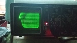
Sorry for being OT, but looking at my scope shot from #16 again the RF eye pattern has around 1.9Vpp. The transport works very well, but the service manual of both the Arcam 170 and the CDM1-MK2 (i.e. CDM4) says it should read up to 1.2Vpp. I searched the forum and found this post, so I checked everything mentioned there but the 1.9Vpp didn't change at all. Everything is resoldered and recapped, I even replaced the RAFOC unit. Is it a problem to have too much RF eye pattern amplitude?
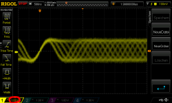
Just checked the RF eye pattern of my Arcam 170 transport with my €400 Rigol DS1045Z, see attached screen shot:
Sorry for being OT, but looking at my scope shot from #16 again the RF eye pattern has around 1.9Vpp. The transport works very well, but the service manual of both the Arcam 170 and the CDM1-MK2 (i.e. CDM4) says it should read up to 1.2Vpp. I searched the forum and found this post, so I checked everything mentioned there but the 1.9Vpp didn't change at all. Everything is resoldered and recapped, I even replaced the RAFOC unit. Is it a problem to have too much RF eye pattern amplitude?
Have you checked the RF the old fashioned way by manually setting the scope to say 1 volt/div (or 0.1/div with a divider probe). Also if using a divider probe (and you should for this) you must calibrate the probe correctly using the scope CAL output as the setting will affect the apparent amplitude of a displayed signal like this.
To much RF implies the laser is being overdriven and that is really the main issue but it can also saturate the photodiode array and lead to 'crushing' of the signal and deterioration of the all important diamond shape in the RF.
To much RF implies the laser is being overdriven and that is really the main issue but it can also saturate the photodiode array and lead to 'crushing' of the signal and deterioration of the all important diamond shape in the RF.
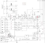
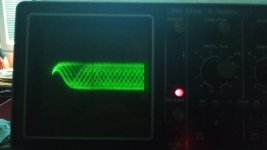
Yes, the scope and probe is calibrated, I used it in the x10 setting, the laser ist adjusted to less than 50mV (on most CDs somewhere around 43mV), focus offset is set around 400mV, and the eye pattern doesn't look clipped on the scope (see attached screen shot). I checked the surrounding of the RF amp IC:
the DC supply to the servo board has -12V, -5.6V, +5V and +10V. The network at pin13 of the TDA5708 is correct (gain control of LF amp), but the network at pin4 (gain control of HF amp) has a 470nF film cap instead of the 150nF (ref 2112) that is shown in the schematic. I checked the other parts around the TDA5708 including the 3 white SMD caps (are they C0G?): the HF blocking cap at pin3 (2102), the DET cap at pin26 (2113), and a cap in the laser supply near pin17 (2114), all of them measure perfectly fine.
the DC supply to the servo board has -12V, -5.6V, +5V and +10V. The network at pin13 of the TDA5708 is correct (gain control of LF amp), but the network at pin4 (gain control of HF amp) has a 470nF film cap instead of the 150nF (ref 2112) that is shown in the schematic. I checked the other parts around the TDA5708 including the 3 white SMD caps (are they C0G?): the HF blocking cap at pin3 (2102), the DET cap at pin26 (2113), and a cap in the laser supply near pin17 (2114), all of them measure perfectly fine.
Attachments
Are you measuring on pin 3 or pin 27? I think you will find pin 3 of the chip (the RF input) is where you will see the raw 1.2 volts pk/pk from the photodiode array.
Original 'manufactured' CD's were made to comply with something called "Red Book Standard".
CDR's were not designed to be exactly "Red Book".
If you have a large collection of CDR's, make sure you hang onto this player. [even as it is]
It may turn-out to be something definitely worth owning 🙂
CDR's were not designed to be exactly "Red Book".
If you have a large collection of CDR's, make sure you hang onto this player. [even as it is]
It may turn-out to be something definitely worth owning 🙂
Hi guys,
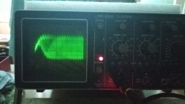
I think the analog scope is working fine now.
However, I cannot find the RF signal. I am looking for on the ribbon cable to the servo board. Is that where I should look for it? I try on a disk that reads normally.
The range is set to:
AMPL/DIV : 200mV
TIME/DIV : 0.1ms
I think the analog scope is working fine now.
However, I cannot find the RF signal. I am looking for on the ribbon cable to the servo board. Is that where I should look for it? I try on a disk that reads normally.
The range is set to:
AMPL/DIV : 200mV
TIME/DIV : 0.1ms
Are you measuring on pin 3 or pin 27? I think you will find pin 3 of the chip (the RF input) is where you will see the raw 1.2 volts pk/pk from the photodiode array.
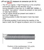
I use pin27 as stated in the service manuals of the CDM4 and CDM1MK2:
Attachments
Hi guys,
I think the analog scope is working fine now.
However, I cannot find the RF signal. I am looking for on the ribbon cable to the servo board. Is that where I should look for it? I try on a disk that reads normally.
With a disc playing normally you will be able to find the RF on the chip the the ribbon cable goes to (on the main board). Normally a quick whizz around the area with the scope will find it without having to look up any circuit details but if you can not locate it then identify the chip and look up its data sheet to find the RF output.
Its worth seeing what you have on the input to the chip. If that is 1.2 volts pk/pk (ish) then I would say it was normal and maybe something different in production.I use pin27 as stated in the service manuals of the CDM4 and CDM1MK2:
I remember an old thread where this came up...
Actually was a pm but 2 volt pk/pk was observed. A CDM2 manual mentions the 1.2 volts pk/pk which is what I always work to and that is the level before any extra amplification of the RF.I remember an old thread where this came up...
What might sound like a silly question. How many real CDs have you tried to play? Could your test CD be faulty?I found the signal and it seems very weak
CD-R - 90mV pp
CD (which he was able to read) - 140mV pp
We really need to be sure exactly where you are measuring to.
At face value it does seem low, also the CDR result can not be used for any measurements. If its correct on a normal pressed CD then whatever a CDR comes out as 'is what it is'. 0.14 volts isn't an expected value and a player wouldn't work down to those levels so I suspect the measurement point or the measurement itself is in error.
Are you taking into account a divider probe? 140mv pk/pk at 50mv/div would actually be 1.4 volts if using a divider probe.
It's like that with every disc. However, I notice that after working for 10 min. then reads each disc normally.What might sound like a silly question. How many real CDs have you tried to play? Could your test CD be faulty?
The next day, however, he does not read CD again until it works a little.
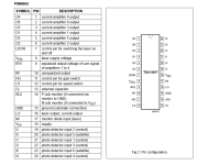
Mooly, the chip is tda1300t. I measure between pin 10 and pin 15.
Oops, the probe was in 10x mode 🙂
Attachments
👍 pins 10 and 15 look good to me. So 1.4 volts pk/pk.
If it won't play when cold then try giving the disc a little turn by hand and see if it reads then. Maybe the spindle motor has a problem. Also it could easily be a cap issue in the power supply as Cyrus like many other similar manufacturers have issues like that.
If it won't play when cold then try giving the disc a little turn by hand and see if it reads then. Maybe the spindle motor has a problem. Also it could easily be a cap issue in the power supply as Cyrus like many other similar manufacturers have issues like that.
Its worth seeing what you have on the input to the chip. If that is 1.2 volts pk/pk (ish) then I would say it was normal and maybe something different in production.
Ok, thanks for the hint! I checked the data sheet of the following IC that takes the RF signal in, in my case it's a SAA7210 which expects a differential signal up to 2.5Vpp, so I guess the Arcam guys intended to set the gain of the TDA5708 higher by applying the somewhat unusual supply voltages and/or with that 470nF cap at the gain control pin. I will leave it as it is because it works flawlessly.
Last edited:
Well, something inexplicable is happening here.
This morning "cold" reads all disks. The only difference is that the scope probe is still attached for measurement to the servo board.
Could this affect in any way?
I also know that Cyrus have redone the servo board "on the fly", interrupted tracks, removed jumper, etc.
I had also come to such a suspicion and spins the motor with an external power supply to warm it up a bit, but it did not work. The construction of this player does not allow me to help the motor with hand. Also done a complete recap of the servo and it looked like the problem was solved, but it wasn't.
This morning "cold" reads all disks. The only difference is that the scope probe is still attached for measurement to the servo board.
Could this affect in any way?
I also know that Cyrus have redone the servo board "on the fly", interrupted tracks, removed jumper, etc.
If it won't play when cold then try giving the disc a little turn by hand and see if it reads then. Maybe the spindle motor has a problem. Also it could easily be a cap issue in the power supply as Cyrus like many other similar manufacturers have issues like that.
I had also come to such a suspicion and spins the motor with an external power supply to warm it up a bit, but it did not work. The construction of this player does not allow me to help the motor with hand. Also done a complete recap of the servo and it looked like the problem was solved, but it wasn't.
You mentioned Focus Offset set to 400 mV. As I understand (perhaps the Service Manual describes a different method) the best setting is zero focus voltage on the focus coil when the detector photodiodes are sharp in focus. This is a mechanical adjustment, by setting the turntable height. Again, my experience is with the CDM-1, your transport adjustment procedure might be different.
Only if it was injecting noise on the signal I guess. A divider isn't going to load anything and I suppose by the same reasoning it shouldn't inject much either.This morning "cold" reads all disks. The only difference is that the scope probe is still attached for measurement to the servo board.
Could this affect in any way?
Has the PSU had a recap as that is where suspicion might lie.
- Home
- Source & Line
- Digital Source
- CD player reads CD-Rs, but not CDs