Hi there!!
Recently I repaired a Philips CD620 that was in a very poor condition, with serious damage in the main board.
After 2 weeks of work, I repaired it and now it’s full working.
Everything was allright until today, by listening the album Dangerous (Michael Jackson). When playing the last tracks I noticed some distortion and artifacts.
When I repaired it I forgot to adjust the lens, so I opened it again to do it.
When I checked the values for Focus and Laser current, it was very very low. So I adjusted the pots to get a better value and now it’s “working fine”.
BUT, here is the problem:
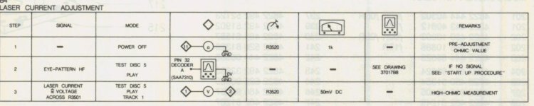
The service manual says that the correct values (using a test cd) has to be:
- 50mV for laser current across a specific resistor.
-400mV (+-40mV) for Focus across certain point and ground.
I have not a test cd, so I took 3 of the best quality cd’s I own and adjusted the pots to get an average value near to the values shown in the service manual.
Example: with cd1 I get 35mV(laser) and 360mV(focus).
With cd2 I get 32mV(laser) and 470mV(focus)
With cd 3 I get 37mV (laser) and 420mV (focus).
The first problem is that I cannot set the laser current to 50mv across the resistor. The max value I can set is 37mV. Is this value too low???
Once adjusted, I tried some other CD’s with different quality pressings and I get very very different values, examples:
I think this values are so far to the ideal.
But, remember that I adjusted the lens with 3 of my best pressings (reflective quality, etc etc) and the average values I can set are: 37(laser) and 400(focus).
So the only thing I can suppose is that the lens is well calibrated but the different quality of my other CD’s makes the lens to work different with very different values for laser current and focus.
The thing here is that now ALL cd’s sounds fine. No distortions. Just pure sound.
Can I be sattisfied with the results? Or is the laser current too low? Service manual says 50mv and I get 37 as much.
Or maybe the diode is in the end of its life?
Postdata. Sorry for my horrible english.
Recently I repaired a Philips CD620 that was in a very poor condition, with serious damage in the main board.
After 2 weeks of work, I repaired it and now it’s full working.
Everything was allright until today, by listening the album Dangerous (Michael Jackson). When playing the last tracks I noticed some distortion and artifacts.
When I repaired it I forgot to adjust the lens, so I opened it again to do it.
When I checked the values for Focus and Laser current, it was very very low. So I adjusted the pots to get a better value and now it’s “working fine”.
BUT, here is the problem:
The service manual says that the correct values (using a test cd) has to be:
- 50mV for laser current across a specific resistor.
-400mV (+-40mV) for Focus across certain point and ground.
I have not a test cd, so I took 3 of the best quality cd’s I own and adjusted the pots to get an average value near to the values shown in the service manual.
Example: with cd1 I get 35mV(laser) and 360mV(focus).
With cd2 I get 32mV(laser) and 470mV(focus)
With cd 3 I get 37mV (laser) and 420mV (focus).
The first problem is that I cannot set the laser current to 50mv across the resistor. The max value I can set is 37mV. Is this value too low???
Once adjusted, I tried some other CD’s with different quality pressings and I get very very different values, examples:
- 22mV (laser) and 560mV(focus)
- 21mV (laser) and 980mV !!!!!!!!(focus)
- 34mV (laser) and 160mV (focus)
I think this values are so far to the ideal.
But, remember that I adjusted the lens with 3 of my best pressings (reflective quality, etc etc) and the average values I can set are: 37(laser) and 400(focus).
So the only thing I can suppose is that the lens is well calibrated but the different quality of my other CD’s makes the lens to work different with very different values for laser current and focus.
The thing here is that now ALL cd’s sounds fine. No distortions. Just pure sound.
Can I be sattisfied with the results? Or is the laser current too low? Service manual says 50mv and I get 37 as much.
Or maybe the diode is in the end of its life?
Postdata. Sorry for my horrible english.
You really should be looking at the RF on a scope to make a determination of quality and amplitude. The 50mv Philips method is looking at the sum of all the photo diode currents in the pickup array and in itself bears no direct relation to laser output as it is a measure of reflected light from the disc.
If the pickup has issues the laser current to achieve this 50mv may be to high for the laser diode. Problems can be mechanical alignment, contamination of the optics or as you say a low emission laser diode.
If the pickup has issues the laser current to achieve this 50mv may be to high for the laser diode. Problems can be mechanical alignment, contamination of the optics or as you say a low emission laser diode.
Thanks for your reply Mooly
I used a scope to look at the Eye pattern. I cannot see "RF" on the service manual, only HF signal. Is it the same?
Here you have a photo of the scope:

As you can see, the Volts/Div scale is set to 500mV. The scope is very very old and the image is not very clear, but the pattern is visible.
When I turn down the Laser Current Pot, the wave amplitude goes down.
If I turn up the pot slowly, the wave increases until the amplitude on the picture. When I increase the Pot (mid way), the very top of the wave makes like an artifact that I describe as spikes on the top of the mountains of the wave. But if I increase a little bit more the Pot, the spikes disappear. So the most beautiful wave I can set is the one you can see.
Also, the laser current voltage is still low. I'm trying a lot of CD's and the highest value I can read is about 35mV.
The thing here, is that maybe (maybe) the service manual is wrong.

As you can see, the manual says that I have to check between points 1 and 2 (or R3501 resistor).
If you look at the board:

Points 1 and 2 are NOT the same as resistor 3501.
If I check voltage between 1 and 2, voltmeter goes out of range (obvious, because this points are wrong). So, what I'm doing is to check directly across the resistor itself.
When I was repairing the unit, I noticed a LOT of errors in the service manual: wrong tags, wrong part numbers, wrong tracks, wrong voltage indicators, etc...
So, maybe something similar is happening here?
Please, could you look at the Philips CD620 service manual and try to determine what are the correct points to check?
Again, the thing here is that the player sounds GREAT. No distortions... just a great and powerful sound.
I used a scope to look at the Eye pattern. I cannot see "RF" on the service manual, only HF signal. Is it the same?
Here you have a photo of the scope:
As you can see, the Volts/Div scale is set to 500mV. The scope is very very old and the image is not very clear, but the pattern is visible.
When I turn down the Laser Current Pot, the wave amplitude goes down.
If I turn up the pot slowly, the wave increases until the amplitude on the picture. When I increase the Pot (mid way), the very top of the wave makes like an artifact that I describe as spikes on the top of the mountains of the wave. But if I increase a little bit more the Pot, the spikes disappear. So the most beautiful wave I can set is the one you can see.
Also, the laser current voltage is still low. I'm trying a lot of CD's and the highest value I can read is about 35mV.
The thing here, is that maybe (maybe) the service manual is wrong.
As you can see, the manual says that I have to check between points 1 and 2 (or R3501 resistor).
If you look at the board:
Points 1 and 2 are NOT the same as resistor 3501.
If I check voltage between 1 and 2, voltmeter goes out of range (obvious, because this points are wrong). So, what I'm doing is to check directly across the resistor itself.
When I was repairing the unit, I noticed a LOT of errors in the service manual: wrong tags, wrong part numbers, wrong tracks, wrong voltage indicators, etc...
So, maybe something similar is happening here?
Please, could you look at the Philips CD620 service manual and try to determine what are the correct points to check?
Again, the thing here is that the player sounds GREAT. No distortions... just a great and powerful sound.
Attachments

Last edited:
The signal on the scope looks extremely noisy. It should look clean and clear like this:

It can be important to use the correct ground points for the scope to get the cleanest signal. Any of the grounds around the chip should be fine.
The manual shows the RF (HF is the same) as being 2.5 volts peak/peak on pin 3 of the RF amplifier. The input is on pin 26 and if you were measuring at the input then your amplitude looks about right (1.2 volts pk/pk) going off the 0.5 volts/div on the scope. Ideally you should be using a divider probe (10:1 probe) and making sure the probe is correctly calibrated to the scope (use the 'Cal' output to do that on the scope). Check it on pin 3 though as that is a low impedance point and less prone to noise pickup.
Thanks again. I’ll try again with your indications.
Well, my english is very bad I didn't fully understand some of what you said:
“The input is on pin 26 and if you were measuring at the input then your amplitude looks about right (1.2 volts pk/pk) going off the 0.5 volts/div on the scope.”
You mean that if I was measuring on pin 26, then the amplitude I shown in the picture is correct?
Edit:
Mehh... forget it... I was measuring at pin 3 (output) so obviously the amplitude is not correct. I bet the laser diode is wearing out. I'll continue measuring with your instructions just for learning... but I think the problem is in the laser.
Last edited:
Mehh... forget it... I was measuring at pin 3 (output) so obviously the amplitude is not correct. I bet the laser diode is wearing out. I'll continue measuring with your instructions just for learning... but I think the problem is in the laser.
It is possible the laser is low emission, also possible to be some issue with the optics but ultimately it all comes down to the same block of parts which is the pickup.
Have you replaced this? If not then do so and also turn the laser power down before before retesting with a new cap.
Wow. Never thought that the laser power could be modified. I checked service manual and the cdm4 itself and didn’t found any pot to adjust the laser power.Have you replaced this? If not then do so and also turn the laser power down before before retesting with a new cap.
Im not at home right now, tomorrow I’ll try first to check Eye pattern with a better ground point. After that I’ll try what you said about the capacitor.
If I understood well, the steps are:
1. Turn down the laser power. But how? And in what grade?
2. Change the cap.
3. Power on the unit and adjust again the laser power. But how? And in what grade?
Thanks.
I thought you had already turned the laser power up and still could not get the required levels ")
If you have not touched the laser power preset then just replace that cap before doing anything else and just see if it is now OK.
Set the RF level using a representative disc (good commercial quality normal CD) to 2.5 volts pk/pk at the point shown in the diagram.
If you have not touched the laser power preset then just replace that cap before doing anything else and just see if it is now OK.
Set the RF level using a representative disc (good commercial quality normal CD) to 2.5 volts pk/pk at the point shown in the diagram.
Oh it was my fault. I thought that this pot acts directly to the light receptors, not to the laser.I thought you had already turned the laser power up and still could not get the required levels
Omg, I was turning full down and up this pot freely. I’s a luck that I didn’t broke anything. Ot maybe yes haha.
Ok so, I’ll turn this pot down, will replace the cap and then turn it up again looking for a good HF amplitude. If in cannot be reached, then the laser (or optics) are bad. In this case one good solution is to buy a cheap player with cdm4/19 and change it (and cross fingers).
Last edited:
Yes, I think the same. But I'm just doing this only for learning. Well I'm so busy right now... In the next days I'll replace the capacitor and do measurements with a good ground point. Thanks for helping me.If the player works fine and there are no skips, I would stop here. Of course replace the capacitor in question. I think your only problem was the insufficient ground point of the oscilloscope probe.
Edit:
Thinking on this cap................ OMG.....
Checked the service manual and is the cap located just in the same corner of the board that was broken. I bought this player in a non working condition because it hit the ground. When opened, I noticed that a small corner of the board was broken and 2 tracks sectioned. I soldered new cables to restore this tracks and the player worked again. BUT this capacitor is just in THIS corner so.... I'll recheck all this section of the board to see if something is wrong...
Last edited:
Ahh! So an unknown historyI bought this player in a non working condition because it hit the ground.
I should have told that first, sorry.Ahh! So an unknown history
I thought that this problem was solved because the player worked again.
SOLVED!
The problem was the CDM4/19. Maybe degraded laser, maybe bad optics (due to the blow).
I have another philips I bought in good condition, and I didn't realize that uses the same CDM. Just changed the CDM (previously i turned down the Laser Pot) and increased slowly until readed the disc. Then, when spinning, measured mV across resistor, and turned up the pot slowly until reach 50mV soooooooooooooooooooooOOOOOo the problem is not in the board!!
I'll put back the original CDM and will use it until it dies. The only thing I can do is to keep watching the second hand market and wait to find a cheap unit mounting the same CDM (and cross fingers that it is in good condition).
THANKS a lot for the help.
Also, happy of knowing that I'm able to repair a broken board
Trust me, the corner on which is located the capacitor you said, was completely sectioned. And the capacitor was hanging by just one leg haha.
Just glued the board, resoldered all components near the damaged zone, and repaired the broken tracks. I know that it's not a hard work for a tecnitian, but I've never done anything like this.
Maybe the drop has had something to do with it
You could (but be very careful) measure the voltage across that 12 ohm resistor from the emitter of the laser regulator transistor and calculate the current. A bad laser will have a higher current draw for a given optical laser output. I think these might use the Sharp LT022MC laser diode and currents from memory would be around 55 to 65 ma.
You could (but be very careful) measure the voltage across that 12 ohm resistor from the emitter of the laser regulator transistor and calculate the current. A bad laser will have a higher current draw for a given optical laser output. I think these might use the Sharp LT022MC laser diode and currents from memory would be around 55 to 65 ma.
12 ohm? You mean on the CDM?You could (but be very careful) measure the voltage across that 12 ohm resistor from the emitter of the laser regulator transistor and calculate the current. A bad laser will have a higher current draw for a given optical laser output. I think these might use the Sharp LT022MC laser diode and currents from memory would be around 55 to 65 ma.
- Home
- Source & Line
- Digital Source
- CD Lens adjustments (Philips)