costnoobject
Hi,
@jean-paul
thanks for adding helpful info.
Do you know Philips CD210?
This is a ugly and shitty Philips plastic crap - but inside TDA1543 - sound is quite good.Almost the whole electronic runs at 5V.
Yesterday evening sold on ebay, price 1.50Euro........!
Tent clock XO2.2 you can get for 139.-Euro +shipping.
Do you think this is worth while?
Suitable clock frequency for TDA1543 is 9.2MHz(datasheet) - not in stock at TentLabs.
For half the clock-price you can buy pounds of electronic crap, if you still like the sound, buy at the very end a new clock.
@audiobart
Do you have actual informations for us?
Is your player still in stock form or just tuned up?
Regards Harry
Hi, I know that one if it is the one with the yellow LCD display. Cheap but reasonably good sounding in stock form. If I am not mistaking it has a Mitsubishi chip driving the TDA and LM833 at the output which can be omitted or replaced. Please remove muting transistors anyhow.
Concerning the clock: Tent is offering the separate clock modules for DIYers. If you buy one of those you will be off much cheaper. I made a small PCB for this.
I think you are wrong with the crystal. Please open it and check the frequency. A better clock (on a separate PCB) can be reused in a lot of other cdplayers with Philips chipsets.
clock frequency
hi,
@jean-paul
yes,you are right, my mistake,
I guess clock frequency has to be doubled to 18,4320MHz, in stock at TentLabs.
Realized this too late,couldn't change post - 30min limit is over!
Regards Harry
hi,
@jean-paul
yes,you are right, my mistake,
I guess clock frequency has to be doubled to 18,4320MHz, in stock at TentLabs.
Realized this too late,couldn't change post - 30min limit is over!
Regards Harry
Hi,
Quantorix:
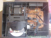
My CD Player is in stock form.take look at the attachments for more info.
The purpose of this thread was to get into cd player mods and learn what is the most cost effective way to upgrade.I don't want to buy kits,or spend lot of money on it.I can do psu upgrades with the parts I have,I also have bypass caps. For clock circuit,if it i is a good upgrade, I am willing to invest some money,but to build one.About I/V stage,I would use a simple resistor followed by an discrete active stage and a passive Bessel filter.I know that I need to make DAC non oversampling to go without the filter.
So guys, suggestions in that direction are welcome.
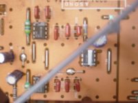
Sorry about the quality of the photos.The DAC is the chip with the white line.The line is factory made.The other two chips are the analog section.
Quantorix:
My CD Player is in stock form.take look at the attachments for more info.
The purpose of this thread was to get into cd player mods and learn what is the most cost effective way to upgrade.I don't want to buy kits,or spend lot of money on it.I can do psu upgrades with the parts I have,I also have bypass caps. For clock circuit,if it i is a good upgrade, I am willing to invest some money,but to build one.About I/V stage,I would use a simple resistor followed by an discrete active stage and a passive Bessel filter.I know that I need to make DAC non oversampling to go without the filter.
So guys, suggestions in that direction are welcome.
Sorry about the quality of the photos.The DAC is the chip with the white line.The line is factory made.The other two chips are the analog section.
Attachments
I can't upload the service manual. If anybody would like I'll e-mail them.
I hope you guys are thinking on ways to help me 🙂
I hope you guys are thinking on ways to help me 🙂
Hi - I think somebody else linked the service manual here. I played around with the 1543 for a while in NOS (that mod's also detailed in the link) with great success. I think I just had a resistor to ground (1.2K) on the output, a 100uf cap bypassed by a 100nf and another resister to ground (100K) - check those values though! One of the biggest improvements I have made on my current TDA1541 player is the addition of a dedicated PSU on the filter (SA7220 in your case I think) just a +5v using an LM317 from a separate transformer, lift a resister or jumper as near to the chip as you can get (make sure nothing else 'feeds' from this), then ground it either under the board on the pin itself or again as near as possible. Keep any decoupling caps in there.
You can go further with these mods by giving every stage a dedicated PSU including the DAC, even running off the original transformer but with a local regulator at least. (For the psu I just used the 'low ripple' schematic from the lm317 datasheet.) I think the DAC can take a higher voltage (8v+ check though!) but I never experimented here.
I thought the NOS tda1543 was great, you can get the dac chips in the uk cheap and the supporting circuitry is dead simple.
I'd be tempted to go NOS, tap into the i2s signal before the dac, then build a separate DAC board, you can experiment with topologies & output stages then without disturbing the rest of the player.
Happy modding!
Thanks josha.
I just had a look at the link,great simple mod.I don't know yet how strong the transformer is.Do you know if it can withstand multiple shunt regs? I would go for capatiance multiplier for the main psu and then shunt reg the other stages.What do you think?
I just had a look at the link,great simple mod.I don't know yet how strong the transformer is.Do you know if it can withstand multiple shunt regs? I would go for capatiance multiplier for the main psu and then shunt reg the other stages.What do you think?
I don't know much about that I'm afraid, from what I gather the idea of two transformers is to keep the digital and analogue supplies separate rather than to reduce the load on the transformers - I must state again though that I don't know much about this! I haven't tried the shunt regs or spowers yet but if the gains are as large as the local regs then I'd like to!
I went for the 317 based psu's as they're very easy&quick to build - I found it helpful to have a another transformer with a 'known to work' rectifier handy to test the psu's before implementing them and always use a fuse!
I went for the 317 based psu's as they're very easy&quick to build - I found it helpful to have a another transformer with a 'known to work' rectifier handy to test the psu's before implementing them and always use a fuse!
Jean-paul,
Thanks for the info.So you think that new clock circuit is worthwhile?
Any sugestions on the output stage,other than the obvius opamp change?
Regards
Thanks for the info.So you think that new clock circuit is worthwhile?
Any sugestions on the output stage,other than the obvius opamp change?
Regards
Are you really considering installing a 116 Euro clock in a player that worths 1.5 Euro?
That TDA1543 is an old DAC, considered low-end even when it was released, there is nothing you can do to improve the sound... With THD of -70..75dB and SNR of 90-96dB will "cover" any clock-related jitter errors.
That TDA1543 is an old DAC, considered low-end even when it was released, there is nothing you can do to improve the sound... With THD of -70..75dB and SNR of 90-96dB will "cover" any clock-related jitter errors.
Last edited:
SoNic_real_one,
No I'm not.I just want to get most out of it with as litle money as possible.This is a learning project for me,and fun also 😉
No I'm not.I just want to get most out of it with as litle money as possible.This is a learning project for me,and fun also 😉
Hi audiobart,
any progress here ? ;-(
For example,
you could ask google for : hifidiy.net.........
may be you would find "clock kit PCB".......useful?
you could ask google once more for : tentlabs.com.........
may be you would find "TentLabs XO", shows you what you
want.................................................................useful?
If you would do this, could this be a step forward for you?
Happy searching
Regards Harry
please remember
forum search
google search
.....and so on......!
Quantorix,
I've searched the net,and this forum.Most mods are like this: chage all electro caps, change output op amps, better psu, better bypass caps. Clock changes are few, mostly recommended for separate dac's units.
So I have decided: better main psu (capatiance multiplier), analog and digital stages with separate shunt regs, new analog stage( passive I/V and discrete buffer).
Maybe I'll go non oversampling,and I'm thinking about clock circuit,but it could be too much.
Opinions welcome.
regards
modding cdp
Hi audiobard,
for a learning project very ambitious............
Before beginning, do an overview what you want to do,
beginn with easy and/or cheap mods,
continue with spending some money for the mods,
end with complicated and/or expensive mods.
Do only one mod, then listen and compare,......use your headphones(should be better ones).
After this do the next mod.
I, for myself, would prefer an easier way :
(NO! rat-nests inside!!!)
1. Clean signal path to output (no muting-no filter!!!) and -
snip out hf-cer-caps near RCA's and rectifier-diodes
also near headphone amp circuit
2. DIL8 socket for LMExxx audio IC and LMExxx headphone-amp IC
(no discrete output!)
3. Change audio-decoupling cap to 10µF tinfoil and 10k to ground = 2Hz
......easy and cheap mods - now listen to a better sound....
4. Change ecaps, Panasonic FC for psu and DAC(=audio!!!), increase value ~10x if enough space (bypass caps X7R) and use OSCON for digital to ground (avoid bypass caps here), if ecap-value is below 10µF use little filmfoil WIMA MKS2, also for all Tantal caps.
5. Change rectifier diodes, use BYV 28 for example
6.Add new regs to digital filter and DAC(and others...), use 78xx/79xx three-leg regs
7. NOS
8. New clock
Don't blow out your money for boutique caps or 50$ regs!!!
All mods are cheap and easy for this learning project
(please read again my previous posts - about coils and clock).
Listen to a new and better sound....
If you like this, you can go further with better regs and other stuff you like best.
Please, keep us informed.........
Happy modding,good luck
Regards Harry
Quantorix,
Thanks for the info.Your recommendations seem good.
Does somebody have anything to add? If not, I'll get on it as soon as possible.
Thanks everybody!
Thanks for the info.Your recommendations seem good.
Does somebody have anything to add? If not, I'll get on it as soon as possible.
Thanks everybody!
Yes.
1. Don't cut those filters out. They are there for a reason. There is no "worldwide conspiration" of evil audio engineers/designers aimed to put them in.
2. In my experience, mutting transitors make no real difference in audio quality (unless they are bad), but without them you will have pops in your speakers and heaphones that might affect their suspensions.
3. NOS sounds like garbage. Same comment about conspirations...
In my opinion, designers of audio equipment build for nice specifications, and they are convinced that a technically better equipment should also sound better. They just learned this in the school. Which company would sell a CD player that has stepped output signal, measurable sampling frequency output, tube analog stage with more than 0.1% THD? The magazines would quickly discredit them and nobody would buy their product (except a few crazy among us).Yes.
1. Don't cut those filters out. They are there for a reason. There is no "worldwide conspiration" of evil audio engineers/designers aimed to put them in.
2. In my experience, mutting transitors make no real difference in audio quality (unless they are bad), but without them you will have pops in your speakers and heaphones that might affect their suspensions.
3. NOS sounds like garbage. Same comment about conspirations...
Jean-paul,
Thanks for the info.So you think that new clock circuit is worthwhile?
Any sugestions on the output stage,other than the obvius opamp change?
Regards
I do. A better clock will almost always pay off but I would search for the least expensive solution concerning the value of this particular low budget cd player. Please check the frequency, I might have a clock left. I don't use cd players anymore for some years now so things are fading but I recall the strange Mitsubishi chip with an odd clock frequency. AFAIK there is not a crystal in this cd player but a ceramic resonator (even worse).
BTW please check this and look for CD210:
http://bakura.nl/tag/philips/
Removing wrongly implemented muting transistors (i.e.collector on signal) is a good mod and you will hear the difference at once. Costs nothing, takes one minute and it is easily reversible.... I haven't experienced cases where i could not hear an improvement. Slight drawback is that you can hear pops with very heavily damaged cd's or at power on. Set the volume to lowest setting when you quit playing music or switch the amp to another input when switching the cd player on. Of course you can use a small muting relay if you like the muting. Please have it shorting the output at power on and not in series with the signal.
http://www.diyaudio.com/forums/parts/199156-mute-transistor-choices-2.html
I would leave the filter where it is and improve decoupling of the new opamps. This is a quite decent sounding cd player when modded right. I recall having changed all caps for Pana FC/FM and the opamps.
Last edited:
- Status
- Not open for further replies.
- Home
- Source & Line
- Digital Source
- CD Clock circuit