This may be another daft question of mine...standby....
I have been messing about with CCS anode loads for a headphone amplifier, and it's taken me the last month to notice that the idle current stability isnt all that great 😡
I have been using two different stages, loaded with different CCS; one BJT cascode delivering up to 1mA (BC557 and ZTX558), and another MOSFET cascode delivering up to 8mA (both devices DN2540).
Both circuits use LEDs to lift the cathode above 0V, but I have replaced the LEDs with bypassed cathode resistors of appropriate value to get close to the same Vg.
The CCS performed the same in either case.
The low current CCS biases up and stabilises nicely, the little TO92 packages heat up and stabilise at about 40 C, according to IR thermometer.
The high current CCS biases up quickly, but then
idle current continues to drift ever so slowly upwards from the setpoint.
At this point no heatsink on the TO220, and they read about 40 C also.
Okay, so a temp. co. That I hadn't bothered to think about.
Besides the obvious, adding a heatsink..., what's the best way to mitigate this? Any clever tricks out there? Maybe adding a PN junction between the D-S cascode connection, and bonding thermally with the CCS MOSFET?
So, I added a small 40mm regulator heatsink to eat DN2540... same result, almost.
Temperature seems to stabilise at a slightly lower temperature, but the CCS still drifts, causing Vp to drift higher over a longer period.
So I set about to use a larger heatsink, and due to space constraints, I settled on a piece of 40x110x5mm copper stock, and mounted both DN2540 on the heatsink, insulated of course...
Now I thought that this is going to make the temp co. effect worse, but the larger heatsink may mean the stabilised running temp is even lower.
OK, admittedly part of me thought the two devices might magically compensate temp. co., in the way the bias diode can when thermally bonded to the output transistor heatsink.
And then I thought again.
The temperature did stabilise lower, but I'd still see a drift of perhaps 5V out of a supply of 150V.
OK, only 3.3% drift...but not good enough!
So I could use a much bigger heatsink, and see a small drift.
Do I need a bigger heat sink?
I drop a total of 50V across the cascode pair, at up to 10mA; so 50×0.01 about 0.5W.
Any ideas how I can reduce this drift further?
Can I use a diode or two between DS cascode connection thermally bonded to one device of the other, to compensate for the drift?
TIA
Last edited:
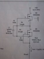
Schematic
For reference, I built this schematic for CCS using DN2540, which was mentioned in another thread, not so long ago.
It has been mentioned in that thread, that turn on transients damaged the capacitor eventually and I have experienced this.
I'll probably build a simple cascode and bin this schematic and check I still have two functional MOSFETs...
Attachments
Just curious, how (in)stable is your plate current? After all it’s supposed to be a CCS, not a voltage stabilizer.
Regards, Gerrit
Regards, Gerrit
Hi,
I was measuring cathode current, but not taking great pains to note it. This was mainly because at least some of the times I was changing the source resistor to get the desired current when warmed up and stable.
I would estimate that, for the say 5 volts of plate voltage drift, mV across 10R changed from perhaps 75mV to 80mV, maybe more, easily 0.5mA change.
I am going to try a basic cascode, LED biased, perhaps that will at least eliminate one thing, the circuit.
Thinking on, it could be temp co of the sense resistor, as I am using 0.6W Welwyn 0.1% and though their temp co is quite good, it's not 0 (also with a 100R WW pot as trim), so heating of the sense resistor is a possibility.
I'd not usually run these resistors at anything more than 50% rating, and often less than that, when using them for instrumentation.
But then, these shouldn't see many volts from the S to G loop...
Last edited:
The Plate load CCS should be able to be relatively stable if the tube(s) are triode(s).
It should meet the CCS data sheet specs versus temperature (but only if you operate the CCS in its linear range). It does have a minimum burden voltage spec in order to be a constant current.
Using discreet parts instead of an IC does require a little more interpretation of the discreet parts data sheets.
Nothing is perfect.
But a tetrode and a pentode/beam power tetrode may create their own changes of cathode current even if the plate current is held exactly constant.
Unregulated screen voltage, Unregulated filament voltage, etc.
But will a 3% change of plate current destroy the tube operation?
How many tubes hold all specs at 3%?
. . . The sky is falling?
Last edited:
Hi, these are triode wired pentodes.
I agree 3% voltage change doesnt seem much
But... current change of 0.5/8mA, 12.5% not good regulation at all.
I think there are issues with my CCS operation, so I will build a different version and test that, over the weekend. I expect I will build a CCS from M.Jones using LEDs as gate voltage refs - I dont know why I didn't do that first, rather than build this wacky circuit!
Since the tubes are DHT, it is possible I am seeing filament voltage changes, under load, but that would be surprising given the rate of change, and the capacity of a D cell.
Last edited:
Ok so some recent measurements, not relying on my memory...
Current after initial switch on goes from 6.738mA to 6.819mA, a change of 0.081mA, roughly 1%.
Hmm...better than I recalled, it seems I lost a zero along the way.
Anode voltage changes from 95V to 105V, a ten Volt change, 6.5% drift.
While I may be splitting hairs, THD performance is optimal at 102V idle plate voltage - a change here of +/- 4V worsens THD by a factor of 2 and tests are less repeatable, as I am constantly chasing plate voltage drift.
Last edited:
Yes, depletion FET CCS have a tempco. But LEDs do as well, and the performance will not be improved much (if at all) by using them.
A stable anode voltage while presenting a horizontal anode load-line is exactly what a "Gyrator" style anode load is designed to do. Check out diyAudio member Ale Moglia's Bartola Valves site, to see a good implementation of this method.
A stable anode voltage while presenting a horizontal anode load-line is exactly what a "Gyrator" style anode load is designed to do. Check out diyAudio member Ale Moglia's Bartola Valves site, to see a good implementation of this method.
Thanks for your response Rod.
There are several gyrators on the Bartola site, the least complex appears to be this one:
https://i0.wp.com/www.bartola.co.uk/valves/wp-content/uploads/2019/02/Gyrator-PCB-Rev08-1.jpg
I have been studying Ale's blog for some time, and was about to build the 1.5mA CCS using LND150 and DN2540 to replace my low current BJT CCS, but I've not had any trouble with that stage.
Ale's 20mA CCS using cascode DN2540 was going to be my next port of call.
Currently, having attached a 6x4 TO3 style heatsink to both DN2540 and current stability seems improved;
I now have a mere 15uA current drift, and this stabilised fairly quickly. Anode volts still climb appreciably, ever towards the rail it seems.
Testing my filament battery, I have 1.07V, which has dropped over time from the 1.2V, I had started with so my feeling is that is is likely to be the filament battery at least to some extent.
I did some experiments where I CCS-loaded an EL34 (mu at the operating point was ~300). I expected the DC plate voltage to be somewhat unstable with temperature since I was CCS-loading a pentode, but actually it was remarkably stable. It only varied a few volts over long periods of operation.
In reference to your post # 7 . . .
So the tubes that have the plate load CCS are DHT Triode Wired Pentodes?
What is the tube type?
Thanks!
So the tubes that have the plate load CCS are DHT Triode Wired Pentodes?
What is the tube type?
Thanks!
Thanks for your response Rod.
There are several gyrators on the Bartola site, the least complex appears to be this one:
https://i0.wp.com/www.bartola.co.uk/valves/wp-content/uploads/2019/02/Gyrator-PCB-Rev08-1.jpg
I have been studying Ale's blog for some time, and was about to build the 1.5mA CCS using LND150 and DN2540 to replace my low current BJT CCS, but I've not had any trouble with that stage.
Ale's 20mA CCS using cascode DN2540 was going to be my next port of call.
Currently, having attached a 6x4 TO3 style heatsink to both DN2540 and current stability seems improved;
I now have a mere 15uA current drift, and this stabilised fairly quickly. Anode volts still climb appreciably, ever towards the rail it seems.
Testing my filament battery, I have 1.07V, which has dropped over time from the 1.2V, I had started with so my feeling is that is is likely to be the filament battery at least to some extent.
Hey,
Sorry, I don't have much time to interact in the forum these days am afraid. Work and family are taking most (if not all) of my time.
As Rod said, FETs have tempco which are the cause of your drift in current. If you get hold of this book: Linden T. Harrison’s “Current Sources & Voltage References”, highly recommended. Linden explores in detail and provide the formulae to get to the zero tempco bias point of the FET. Given the variance of the FET parameters, it's just indicative. I covered some of this in my lecture at ETF.18. You can read it here (have a look at page 15 in particular): ETF.18 DHT Preamps Lecture – Bartola(R) Valves
For the LND150 voltage reference, a current between 300 to 500uA is ideal. I haven't measured the DN2540 but has not great tempco. In fact, looking at the datasheet, assuming minimum IDSS=150mA and a VGS(off) = 2V, I(0TC) is about 15mA. Above that, you get worse tempco. Again, DN2540's parameters (IDSS and VGSth) are all over the place so it will depend on the device.
There are more complex circuits to implement to improve tempco on a 2-pole CCS, you can move to a bipolar CCS with PNP cascode though and with a more stable voltage reference.
Alternatively you can implement a voltage controlled CCS (VCCS) or gyrator as is known. I use this circuit in a mu-follower version and take the output to parafeed from the low impedance (1/gfs) node from the "gyrator" board.
A bit more parts, but with a sterling sound and high PSRR. You can build your own PCB or protoboard to put the circuit in it. Not a big job.
Good luck!
Yes, ~10% drop in filament voltage is too much for high anode-current stability.
As it turns out, bringing the filament voltage back up to where I wanted it, helped a great deal. Until I found...
In reference to your post # 7 . . .
So the tubes that have the plate load CCS are DHT Triode Wired Pentodes?
What is the tube type?
Thanks!
The tubes are triode wired Russian rod pentodes (1J29B & 1J24B)
When I saw large step changes in anode volts I investigated the circuit more closely.
I found a cold solder joint, which was unreliable, at the connection of anode and g2.
The stability situation, whilst still a little problematic, is now easier to account for, now there is only one "fault".
Ale,
Family and work are important parts of our lives, no need to apologise - I too, spend the majority of my time working or caring for my children.
Thank you for your time and detailed reply, I will be sure to look up the referenced text.
The gyrator you suggested, or the version Iinked to (rev08) is probably my next course of action - after the children are asleep!
However, my latest result with my current CCS is improved, anode voltage now rises about 5 Volts over the course of 20 minutes, so setting a lower anode voltage and allowing the temp co to raise it to where I want, at temperature stability, seems to work well enough - of course, when the circuit gets a case to enclose it, I will need to test again to see where the CCS stabilised.
Thanks to all the members for all their helpful advice!
- Home
- Amplifiers
- Tubes / Valves
- CCS setpoint vs temperature stability