ErikdeBest said:Great suggestion by Shoog. And about question 2 - I imagine you already have an amp up and running? So you should know the current through the EL34's, or you can easily measure it. So, take 1,2 and divide it through the current (in mA): this is the value for the programming resistor. Now just install this in the cathode circuit, as shown by Broskie.
Don't forget heatsink
Erik
i have an EL34 SE amp made, but not a PP one, can I just assume the same plate current, and voltage? It will be the same power supply.
by Broskie? do you mean the circuit in the link?
http://www.glass-ware.com/tubecircuits/Tube_Auto_Biasing_2.html
What value should the cap be? also, the schematic alread calls for a 220k going to the ground from the coupling cap instead of 1m, which one should I use
Hi Alexmoose
SE makes things even easier - better is a matter of opinion 🙂
Just for clarity...your amp has got auto bias right now? I mean, a resistor and cap parallel, to set the bias? If so, you don't have to worry about plate voltages and so. The LM317 will drop in the circuit in place of the resistor, and it will develop the same voltage across it as the resistor is doing right now (you remember, magic). So, the only thing you have to do is knowing how much current goes through the EL34, use this value to calculate the current setting resistor, take out the big resistor that is there now and install the LM317 + current setting resistor in place, as Broskie mention in his article. You can keep the same capacitor. You can use the 220k resistor from grid to ground (what value is the coupling capacitor?)
I would you suggest you give another very good read at the article to understand it throughly. That will make a better learning experience!
Erik
I have an SE one built, and yes it has an autobias, and I will instate the lm317 in that amp as soon as I can, but the PP amp that I am making has no capacitor there. should i just leave it out of the circuit?
my current SE amp has a coupling cap of .1uf
the new PP amp that is pre-construction's coupling cap is .33uf
my current SE amp has a coupling cap of .1uf
the new PP amp that is pre-construction's coupling cap is .33uf
The cathode bypass cap is absolutely essential to the operation of a cathode CCS. The CCS has a very high AC impedence (about 250K) and without the bypass cap will simply surpress the signal. The bypass cap should be sized at the same value as the one used in your SE amp.
Heres a question, is the proposed EL34 PP amp operating in pure class A. If not then using a LM317 will not work, as it will try to fight the transition into AB operation. Does the original circuit that you are copying indicate the expected current through the Tube. These are the two most essential questions which will determine whether the circuit will work at all.
Shoog
I came across this somewhere:
"In the Nat Semi catalogue graphs indicate that over 2kHz , these LM317s are completely useless . Ok if you bypass with a capacitor but then not a very good current source at all . I've tried them underneath EL84's (one per side) , all the things did was to keep the currents balanced . Far better off with a battery biased mosfet or better still a cascode!"
So how about some suggestions for a cascode circuit? Morgan Jones has designs in his book (page 134), and I believe that for an output tube it's a case of putting in a more substantial device than the BC549 used in the lower position in the cascode. I guess a MJE340 with a heatsink would be a start. I intend to try this on an EL84 amp I have. If my memory is correct I tried a 317 and thought it sounded awful - tight and good bass, but treble with an edge like sandpaper.
I believe that for an output tube it's a case of putting in a more substantial device than the BC549 used in the lower position in the cascode. I guess a MJE340 with a heatsink would be a start.>>
Sorry I'm being a bit vague here, I meant keep the BC459 in lower position in the cascode and put a MJE340 in the upper position (with heatsink). This requires a -15v reference supply
Sorry I'm being a bit vague here, I meant keep the BC459 in lower position in the cascode and put a MJE340 in the upper position (with heatsink). This requires a -15v reference supply
Okay, I am pretty sure I need to use the circuit for up to 100v of bias as seen below, but does anyone know what values of Zeners I should use?
here is the circuit
An externally hosted image should be here but it was not working when we last tested it.
here is the circuit
I came across this somewhere:
"In the Nat Semi catalogue graphs indicate that over 2kHz , these LM317s are completely useless . Ok if you bypass with a capacitor but then not a very good current source at all . I've tried them underneath EL84's (one per side) , all the things did was to keep the currents balanced . Far better off with a battery biased mosfet or better still a cascode!"
So how about some suggestions for a cascode circuit? Morgan Jones has designs in his book (page 134), and I believe that for an output tube it's a case of putting in a more substantial device than the BC549 used in the lower position in the cascode. I guess a MJE340 with a heatsink would be a start. I intend to try this on an EL84 amp I have. If my memory is correct I tried a 317 and thought it sounded awful - tight and good bass, but treble with an edge like sandpaper.
The fact that the LM317 has a very low impedance over 2Khz shouldn't make much difference. The overall impedance of the cathode is the combined parallel impedances of the capacitors and the LM317, so whether the LM317 is high or low won't make a heap of difference. What is critical is that DC supplied is constant. Even if the LM317 drops its impedence to 10ohms, the caps should still dominate.
I question you assertion that it sounded edgy as sandpaper because two well respected designers (diyparadise and Tubecad) have both advocated its use in this application with positive results. Is it not equally possible that in your implementation there was instability which was causing your "edgyness" . If you think there is some other effect going on - what is it?
It is equally possible that the application of the LM317 CCS is shining a dazzling light on the inadequacies of other parts in the system. Its certainly getting that way with my system now.
There are a number of other possabilities for the cathode which have been mentioned in this thread. One is the "bias block", and certainly there are versions of Morgan Jones CCS which have been designed for this application. There are extensive threads discussing this topic which can easily be found with a search.
Shoog
Okay, I am pretty sure I need to use the circuit for up to 100v of bias as seen below, but does anyone know what values of Zeners I should use?
The LM317 wants about 10V over it. The Zeners need to eat up the difference between the bias voltage and the 10V the LM317 wants. So in order to decide on the Zeners you need to set the bias voltage. Using two Zeners will split the voltage between them, so that even if one of them fails the LM317 should still survive.
Shoog
Shoog said:
The LM317 wants about 10V over it. The Zeners need to eat up the difference between the bias voltage and the 10V the LM317 wants. So in order to decide on the Zeners you need to set the bias voltage. Using two Zeners will split the voltage between them, so that even if one of them fails the LM317 should still survive.
Shoog
Okay, this makes sense, so the number of Zeners used is really not vital, I could use more should I have too, but I should use at least two. so I should keep the burdern on the lm317 as low as possible, so should a Zener fail, the LM317 will pick up the slack right? however I should look for certain voltage drop across each Zener, so the 317 can accomidate for transients
My understanding is that the bias voltage is the maxmum voltage the LM317 will see, the transients will reduce the voltage over the Lm317 - not increase it.
Shoog
Shoog
Don't forget to use a small bypass cap on the input of the LM317 if the main caps are mounted any distance from the regulators. Without it you might get that "edgy" sound.
Shoog
Shoog
that sounds resonable. what value of bypass cap should I put in? I think the bias circuit will be on a seperate board. I am actually going to make the bias circuit my own by combining the 317 with high current LEDS
I used 0.1uf Seemed to mellow things out, which suggests there was instability before.
I'am not certain that using LED's will work, but i'am also not certain how you will use them. Since the LM317 needs to be bypassed, by lowering the AC impedence you make it more difficult to adequately bypass the LM317 in that you need much bigger caps. If you are simply going to replace the Zeners with LED's then that should work without any difficulty.
Shoog
I plan to replace one zener with an LED, so it will double as an "on" light, and because I have easy access to them
9.5 years later but I thought I'd mention what worked for me.
Instead of an LM317 I use TL783. It's rated at 1/2 the current but 100V. I'm using them on 6P3S tubes in triode with 450V B+. They are bypassed with 10000uf capacitors in series with 10k and parallel diodes in anti-current. And the cathodes are capacitor coupled with 1000uf (Allowing peak excursions into Class AB1) Using a CCS instead of a resistor increased the efficiency by almost 100 percent.
Instead of an LM317 I use TL783. It's rated at 1/2 the current but 100V. I'm using them on 6P3S tubes in triode with 450V B+. They are bypassed with 10000uf capacitors in series with 10k and parallel diodes in anti-current. And the cathodes are capacitor coupled with 1000uf (Allowing peak excursions into Class AB1) Using a CCS instead of a resistor increased the efficiency by almost 100 percent.
Weird how 10 years later i'm exploring the same things. July 2006 was a month before I left for college. 10 years later I have an EE degree so these concepts make a whole lot more sense to me.
Why did you opt for the TL783 over the 2 NPN/2 LED CCS. Seems cheap and robust to me.
I'm planning on a bench test of a CCS loaded parafeed amplifier later this week. If this fails I was going to try and convert it to Shoog's DC7 MKII
Why did you opt for the TL783 over the 2 NPN/2 LED CCS. Seems cheap and robust to me.
I'm planning on a bench test of a CCS loaded parafeed amplifier later this week. If this fails I was going to try and convert it to Shoog's DC7 MKII
Weird how 10 years later i'm exploring the same things. July 2006 was a month before I left for college. 10 years later I have an EE degree so these concepts make a whole lot more sense to me.
I'm in a similar place actually 🙂
Why did you opt for the TL783 over the 2 NPN/2 LED CCS. Seems cheap and robust to me.
Mainly because they wire in just like the LM317 would so it's a simple drop in replacement. They're also about $1 CAD a piece on eBay at the moment 🙂
I also wire point to point so one heat sink is easier to work around.
I'm planning on a bench test of a CCS loaded parafeed amplifier later this week. If this fails I was going to try and convert it to Shoog's DC7 MKII
Nice. I think you'll be pleased with the result.
Another reason I went with CCS was to try toroidal power transformers as outputs (and because there's no DC mismatch they actually sound damned good).
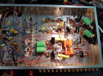
This was my first integrated amp attempt so it has an 6N1P/6N2P Aikido phono, 6N5P/6N6P Aikido headphone, 6N1P ACF buffer, 6N1P CCDA driver, and a 6N2P doing floating paraphase into the CCS loaded 6P1P tubes biased at 56 ma. 300V B+ in tetrode connection.
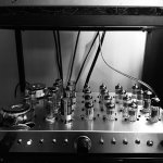
The power supply is external. And in this picture almost everything is wired except the RCA's and the switch. Thankfully ethernet cable is pre twisted, there were almost 100 connections to solder!
Oh and the chassis was reclaimed from scrap. That's why it's kind of rough.
Koda
Attachments
Last edited:
- Status
- Not open for further replies.
- Home
- Amplifiers
- Tubes / Valves
- CCS current sink in the output of my 2 tube 6080 amp.