Why not go LTP on the output stage?
Your circuit doesn't allow any grid current anyway, so no need to venture out of class A.
Simple experiment;
1) disconnect the caps bypassing the CCS's.
2) disconnect one CCS per tube pair
3) connect the remaining CCSs (one per tube pair) to both tubes' cathodes
4) adjust the CCS current to double
10 mins of soldering, and easy to reverse. Probably smart to try this at triode mode at the same time.
Thanks for the advice - as I am using pcbs with the valve holders on the solder side protruding through the chassis, disconnecting and removing the board takes quite a bit of time so experimenting is rather difficult. From the foregoing I am reluctant to use a CCS at all. I guess that I should have used point to point connections instead so that any changes would have been simpler instead of trying to make everything as 'neat' as possible! I assume that LTP stands for long tailed pair?
For most people cathode resistor bias is best. Nothing to adjust, and it automatically copes with valve ageing and sample variation. There is no reason to set an output current to some precise value, as valves are not that fussy. However, people like to feel they are doing something more complicated than naive boring engineers do, and surely something more complicated must sound better?
I have been making many SEP EL84 amps lately, and I have been using the LM317 as a CCS to set the bias on the cathode. For the EL84 and using an LM317 I use a 27ohm resistor + a bypass cap per tube. Previously, I always used a cathode resistor and bypass capacitor. But in head to head tests the amp with the lm317 sounded better. Specifically, in the area of the low frequency. Bass is fuller and deeper. IME, it is hard to get a significant improvement in that area so I like that aspect. As far as problems I have experienced none with my amps. I have made 5 of them and converted another 4 to CCS. All the amps are SEP el84 except 2 are 7591 amps and 1 is a KT88 amp. The EL84 tubes I use are the Russian 6P14P or USA and British EL84. I am not an engineer just a DIY'er so, I thought I would relate my experiences. cheers, Dak
Many ways to skin this cat. I use a constant voltage source/sink in the cathode of my SE 833 amps. They're direct coupled amps with 215V on the 833 grid so I need substantially higher V than that in the cathode. Using an adjustable shunt regulator in the cathode allows easy adjustment of the 833 current (160mA); the TO-247 pass MOSFET of the regulator burns off 44W at idle sinking the output tube current. Since the reg has its own standing current of 15mA through the MOSFET at all times there is no problem with overload recovery even at tube cutoff. No bypass cap needed of course.
.
.
Last edited:
I gather most responders are not liking a CCS on the cathode of the output tube in this scenario of a PPP EL84 amp. While I can not say for certain that an LM317 used as in combination with a 27 ohm resistor + 100uf x 25v bypass cap (for an el84) will work for Martin's amp I know that it works and sounds good in the 8 SEP (single ended pentode) that I have made. 4 amps were first time build EL84 made from console amps, 3 were conversions from previous cathode bias amps and 1 was a ground up build of a KT88 amp. As I mentioned these are a SEP stereo amps.
In head to head comparison of the previously cathode biased amps to LM317 VR used as a CCS the improvement in sound was readily discerned. Specifically, the low frequencies are much better. Bass is deeper and more controlled. IME, to achieve an improvement in this area is quite difficult in an amplifier and is mostly achieved by changing to a speaker with a bigger woofer or use a powered subwoofer.
The implementation of the LM317 in place of the cathode bias resistor is not much more than the resistor/cap, requiring just the added part in the same circuit. The main concern is the temperature limit for the part which needs to stay below the absolute limit of 150 deg. Centigrade. I have seen some installations with the part on a circuit board mounted topside or in a cooler area of the amp. In my builds I have been mounting them close to the output tube without problems. But , my amps have cooling holes around the output tubes. Reliability has not been an issue so far. I have not had a single failure yet although I do revolve my amps quite often, and usually I play them for 2 to 5 hours. 4 of the EL84 amps I have sold and no problems reported. I just thought I would present a different view of this issue. Cheers
A thought (getting old and slow) - transformer manufacturers quote loaded voltages so I guess that the 290v would be the loaded value and therefore quite safe and appropriate for el84s?
That depends...
In the electrical power industry, it's pretty much universal for transformer manufacturers to quote the secondary voltage as the full load value.
For transformers for electronics, some manufactuers quote the unloaded value. That's actually of value, as it makes it easy for circuit engineers to ensure that diodes, capacitors, etc will always be within ratings - especially with solid state circuits (which of course have been 99.99% of the market for 50 years), which have idle currents just a small faction of the full drive/load value.
is there an unwritten convention somewhere that says, schematics showing voltage readings are based on hot filaments? or is it a natural assumption?
Ahah! That is what you were on about. Your terminology was a bit obscure in your first post, and in your use of the word "quiescent". However I can't think of a way just now to put it any better.
More importantly, does this downward shift in "quiescent" current (equivalent to an increase in bias voltage) result in distortion? Well, as far as the tube is concerned, it's an increase in bias the same as the increase in current in a bias resistor, except somewhat more so.
So, while transient handling is improved with a CCS, steady state harmonic distortion can be expected to be worse than with cathode resistor bias.
You are a sharp thinker, DF96. I never thought of it that way until now.
What I wrote there is garbage. A senior's moment. My only excuse is that I was tired and wrote it just before going to bed after a long day.
It's really quite simple.
With cathode resistor bias, under strong drive the tubes increase their mean cathode current. Under overdrive the current increases still more. This leads to two problems:-
1) The increased current leads to increased bias voltage (V= I.R in the cathode resistor) so the tubes now operate closer into teh curved part of the grid characteristic near cutoff. So steady state distortion increases slightly,beyond what it would be with fixed bias.
2) When the strong or over- drive ceases, the byapass cpa is charged up to the increased voltage. Until it discharges into the cathode resistor, the tube remains overbiased and any quiet parts of the music get increased distortion.
With const current source bias, the situation in both respects is worse. With strong drive or overdrive, the tube still tries to increase current. The CCS will prevent this. It does this by increasing the bias voltage - an increase much greater than for cathode resistor bias.
Not only that, on recovery from strong or over- drive, the bypass capacitor charged up more, has to discharge into a CCS - a high impedance. So the distortion after overdrive is not only worse, it stays worse for longer.
So there is nothing good about using CCS's in cathode circuits. They cost more, they are less relaible, and they cause more distortion. Not just more steady state harmonic distortion, but poor overdrive recovery.
Why not go LTP on the output stage?
Your circuit doesn't allow any grid current anyway, so no need to venture out of class A.
Simple experiment;
1) disconnect the caps bypassing the CCS's.
2) disconnect one CCS per tube pair
3) connect the remaining CCSs (one per tube pair) to both tubes' cathodes
4) adjust the CCS current to double
10 mins of soldering, and easy to reverse. Probably smart to try this at triode mode at the same time.
Bad idea.
Using a common DC tail, a stronger tube will over bias the weaker tube. So as tubes age, any small difference in emission or gm gets magnified, unbalacing push pull operation and increasing distortion.
This effect happens to a certain degree with a common cathode resistor. It's much worse with a common CCS.
And as the increase in distortion is gradual, you get acclimatised to it, and eventually realise you are not enjoying your music so well and wonder why. Untill you do notice the distortion and get new tubes.
For best performance and effective tube life, each tube must be separately biased. Cross connect the cathodes with capacitors so that gain is not compromised, and there is LTP action for signals (AC), making for dynamic balance as well as static balance.
Many ways to skin this cat. I use a constant voltage source/sink in the cathode of my SE 833 amps. They're direct coupled amps with 215V on the 833 grid so I need substantially higher V than that in the cathode. Using an adjustable shunt regulator in the cathode allows easy adjustment of the 833 current (160mA); the TO-247 pass MOSFET of the regulator burns off 44W at idle sinking the output tube current. Since the reg has its own standing current of 15mA through the MOSFET at all times there is no problem with overload recovery even at tube cutoff. No bypass cap needed of course.
.
Tube manufacturers advise against fixed bias and DC coupling though. That's because the operating conditions will change over time as the tubes age. Cathode resistor bias provides a DC -ve feedback so that operating conditions don't change so much. And without DC coupling, drift of driver tube emssion doesn't get amplified by the output tube.
DC coupling in tube circuits is not a good idea, except for things like an input stage driving a concertina phase splitter, where the splitter has no gain and can't amplify the drift, or in volatge amplifers with resitive loads, which allow considerable DC negative feedback to stabilise things.
Really, the idea of having an amplifier is to enjoy the nice music, not in adjusting to specification at frequent intervals.
is there an unwritten convention somewhere that says, schematics showing voltage readings are based on hot filaments? or is it a natural assumption?
It's a natural assumption, and a convention.
It is also a convention, that unless otherwise stated, voltages are as measured with no signal, and all user controls (volume etc) at mid position.
It was also a convention back in the Years Before Transistors Were In Everything that voltages on schematics were measured with an analog multimeter of specified sensitivity, typically 20,000 ohms/volt (AVO-8) or 10,000 ohms/volt.
This is important to know, as the measured voltage on anode and screens in low level stages could be very different to what you would measure with a modern digital multimeter.
For example, consider a pentode used as a preamp stage with a 470 kohm screen resistor. A 10kohm/V analog multmeter on the 100V range will offer a shunting resistance of 1 megohm, pulling down the voltage by up to about 30%. Measuring with a VTVM was usually more accurate, as they usually had in put resistance of 11 megohm. But circuits showed what you would see with an ordinary 10 kohm/V multimeter.
Some modern digital multimeters have 100 megohm inputs, and will read much higher in tube preamp circuits than either analog multimeters or VTVM's.
Another thing to note:-
With commercial circuits, the voltages shown on schematics were those measured with all components "bogie", that is dead centre in their manufacturing tolerances - tube with gm at the datsheet value, resistnces exactly their marked value, etc. So when you are working on a repair, you know that the circuit shows volatge that are typical, and what you get can be a litle bit above or a little bit below, but within a few percent in any case. Tube manufacturers used to supply special "bogie" tubes, and sometimes high and low tolerance tubes to equipment manufactuers for prototyping purposes. Manufacturers ran calibation laboratories whose specific mission was to ensure by regaulr scheduled testing that all meters and instruments met specified accuracy.
With circuits published in magazines for home construction, voltages shown on the published cicuit will usually be what was measured on the author's one and only prototype, with his multimeter. Since he certainly will NOT have gone to the trouble of obtaining bogie parts, or even ensuring his multimeter has accurate calibration., the voltages he got might be typical, and might well be untypical. Perhaps even quite abnormal. Exception to this were circuits based on manuafctuer's application reports, such as the GEC (eg "88-50") and Philips tube circuits, which can be taken as properly engineered and tested to manufacturing standards.
Beware, and don't leave brain in nuetral when working off published circuits, particularly home construction circuits.
Last edited:
Tube manufacturers advise against fixed bias and DC coupling though. That's because the operating conditions will change over time as the tubes age. Cathode resistor bias provides a DC -ve feedback so that operating conditions don't change so much. And without DC coupling, drift of driver tube emssion doesn't get amplified by the output tube.
DC coupling in tube circuits is not a good idea, except for things like an input stage driving a concertina phase splitter, where the splitter has no gain and can't amplify the drift, or in volatge amplifers with resitive loads, which allow considerable DC negative feedback to stabilise things.
Really, the idea of having an amplifier is to enjoy the nice music, not in adjusting to specification at frequent intervals.
That's why I have a big old 3 1/2" Simpson milliammeter on the front panel. I can read it from my listening chair. An occasional glance at it assures all is well. It's actually been very stable for more than a year now.
Attachments
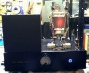
That big ugly naked trasmitting tube's anode is glowing red.
Yeuuchh!
But transmitting tubes with thoriated tungsten flaments are inherently more tolerant than oxide coated filament tubes. They are made with much more care.
Yeuuchh!
But transmitting tubes with thoriated tungsten flaments are inherently more tolerant than oxide coated filament tubes. They are made with much more care.
I have been making many SEP EL84 amps lately, and I have been using the LM317 as a CCS to set the bias on the cathode. For the EL84 and using an LM317 I use a 27ohm resistor + a bypass cap per tube. Previously, I always used a cathode resistor and bypass capacitor. But in head to head tests the amp with the lm317 sounded better. Specifically, in the area of the low frequency. Bass is fuller and deeper. IME, it is hard to get a significant improvement in that area so I like that aspect. As far as problems I have experienced none with my amps. I have made 5 of them and converted another 4 to CCS. All the amps are SEP el84 except 2 are 7591 amps and 1 is a KT88 amp. The EL84 tubes I use are the Russian 6P14P or USA and British EL84. I am not an engineer just a DIY'er so, I thought I would relate my experiences. cheers, Dak
I have found similar, in that a common CCS in the kathode circuit sounded clearly better than a common resistor. Actually, it was combination biased with interstage transformer in Class A, push pull 2A3/300B.
Ludwig
Gentlemen, thank you for an enlightening and interesting discussion. My impression that working with valves is a lot more involved than a simple ten want transistor amplifier! As I will never run the amplifier at anywhere near full power and as I have time on my hands I will run the amp for a couple of weeks with the CCS arrangement then change to the standard bypasses cathode resistor to check if there are any (noticeable) audible differences. I must admit that using only bypass resistors - one per valve - and coupling the each cathode pair with a NP 100 mf cap sounds logical and interesting. Also worth a try.
. My impression that working with valves is a lot more involved than a simple ten want transistor amplifier!
That depends on your own knowlege and on how you look at it.
It is relatively simple to get good results out of a tube amplifier if you don't depart much from circuits issued by tube factory application notes. The mathematics required to correctly engineer a typical tube circuit are not particularly involved.
It is a lot cheaper to get better quality audio from solid state. And not too difficult to get reasonable sound. But to to get excellent performance out of solid state demands a lot more engineering, mathematical, and engineering experience than does a tube amp. Some distortion mechanisms require specific test procedures to highlight, but never the less can have a very noticeable effect of perceived audio quality.
There are some subtleties in getting the best audio quality out of tube circuits, but if you get them wrong they don't have a major impact.
So, if you lack engineering experience and lack a full set of instruments, you may well get better results with tube circuits.
But don't waste your money on recent fads like ccs cathode bias circuits, const current filament energisation of directly heated tubes, and the like. As DF96 said in post #12, people think that these "innovations" must improve the sound as they think that surely these things that were not done by old engineers must make the sound better. They don't.
How about instead of a chip regulator, you use a MOSFET amplified Zener diode...?
Nicknamed, a 'Mozener' circuit. Try a search here under Mozener, sould turn it up....
Nicknamed, a 'Mozener' circuit. Try a search here under Mozener, sould turn it up....
Beware of hobbyists that claim A is better than B, when they are relying on just their own experince and offer no logical technical argument to back it up. Especially if their claim is not backed up by neither logical expanation nor meaured data where how these measurements were done.
The medical industry is well aware of the placebo effect, and the power of positive thinking. Drugs are proved out by large scale trials done on a double blind basis. No doctor would ever make up his mind about a drug on the basis of a single patient - not if he's going to be allowed to continue practice.
When people spend money, there is what I call the VW Beetle effect - something that any mechanic can tell you is a rubbish car - but thousands loved the horrible dangerous overheating thing. The mind has an amazing ability to convince itself that something that cost you is good - it avoids embarrasment.
What makes you think it's different for some chap's latest tube amp?
How about instead of a chip regulator, you use a MOSFET amplified Zener diode...?
Nicknamed, a 'Mozener' circuit. Try a search here under Mozener, sould turn it up....
A generously rated zener diode in the cathode circuit is essentially a form of fixed bias - with the advantages (slightly lower distortion, no overdrive consequences) and dissadvantages (performce affected more than it should be by tube aging, greater risk of catastrophic tube failure) of fixed bias. To protect the tubes, you need to have atleast some resistance in series with the cathode per tube manufacturer recommendations.
Using a MOSFET to make a big zener out of a little one, just adds a serious failure mode to the fixed bias disadvantages listed above. Sub-microsecond internal tube shorts (normally not damaging and something that happens in tubes from time to time) can take out the MOSFET. And as Sangram (Post #16) discovered, if the cathode bias circuit fails into a short circuit, it will destroy the tube as well. You need very carefull layout and palcement of capacitors to reduce this problem.
These comments also apply to integrated zener-MOSFETs, such as the 1N5274BRL. MOSFETS made with internal protective zeners shoukd be more reliable - these internal diodes cannot be used for regualtion of course.
Generously sized standard zeners are inherently fairly rugged and don't tend to fail when hit with sub-microsecond pulses.
If you must use an amplified zener, do it with a diffused type power transistor, not a MOSFET. There is no performace down side, and diffused type transistors are much more tolerant of abuse than are MOSFETS. Because of their susceptability of shorting out when hit by high volt but extremely short pulses, MOSFETs have no place in tube circuits.
Last edited:
That big ugly naked trasmitting tube's anode is glowing red.
Yeuuchh!
But transmitting tubes with thoriated tungsten flaments are inherently more tolerant than oxide coated filament tubes. They are made with much more care.
It's supposed to glow red, it's graphite so it's extremely rugged. The glow is a feature.
Ugly to you, pretty as Scarlett Johanssen to me. To each his own.
.
Last edited:
- Status
- Not open for further replies.
- Home
- Amplifiers
- Tubes / Valves
- CCS current regulators for OP valves