
Yes. I always keep a couple of cheap phono leads with no earth connected on one end just for this kind of testing.
The other option is to switch the earths as well as the signal.
The other option is to switch the earths as well as the signal.
Thanks Al,
I'll disconnect them tonight and see what happens. I appreciate the suggestions.
Terry
I'll disconnect them tonight and see what happens. I appreciate the suggestions.
Terry
No problems mate. Many's the time I have spent hours stuck in racks trying to get earthing issues sorted. When you get there, it will feel so good!
Hmmmmmmmm
Dratted Hum! Still haven't got rid of it. Tried lifting the gound on the inputs, and the hum went from mildly irritating to deafening. Tried combining everything to a single star ground with no effect. Tried inserting resistance between the star ground(s) and the circuit input (-ve circuit input is grounded for single ended inputs) with no effect. Checked every connection with a multimeter to ensure no cold solder joints. AAARRRGGGHHH!!!!!!!!!
The thing I can't figure out is why I had no problems back when I only had one balanced and one single-ended input connected to the input switch, but now that I have added three more SE and another balanced input I am having problems. At least the hum level is low enough that I can ignore it unless I turn the volume way up.
On an aside, I also discovered that Fluke 97 Scopemeters are awfull! The instruments self-noise is higher than most of the interesting things I want to try measuring.
Re: Hmmmmmmmm
Hey Tin Man, try this, connect a length of wire from the case of your Preamp to the case of your source and the case of your Amp., then wire it to the ground on a three prong plug and plug it in the wall. This will pull all the grounds to the same potential regardless of internal wiring schemes. Use 14 or 16 gauge wire and be sure to check for current flow with an ammeter just to ensure you do not have a leak from a live circuit to a chassis.
I usually back out a screw on each case and use a crimp on eyelet under each screw. If your humm persists after this I do not think it is a ground issue your having.
Regards
Anthony
metalman said:Dratted Hum! Still haven't got rid of it. Tried lifting the gound on the inputs, and the hum went from mildly irritating to deafening. Tried combining everything to a single star ground with no effect. Tried inserting resistance between the star ground(s) and the circuit input (-ve circuit input is grounded for single ended inputs) with no effect. Checked every connection with a multimeter to ensure no cold solder joints. AAARRRGGGHHH!!!!!!!!!
The thing I can't figure out is why I had no problems back when I only had one balanced and one single-ended input connected to the input switch, but now that I have added three more SE and another balanced input I am having problems. At least the hum level is low enough that I can ignore it unless I turn the volume way up.
On an aside, I also discovered that Fluke 97 Scopemeters are awfull! The instruments self-noise is higher than most of the interesting things I want to try measuring.
Hey Tin Man, try this, connect a length of wire from the case of your Preamp to the case of your source and the case of your Amp., then wire it to the ground on a three prong plug and plug it in the wall. This will pull all the grounds to the same potential regardless of internal wiring schemes. Use 14 or 16 gauge wire and be sure to check for current flow with an ammeter just to ensure you do not have a leak from a live circuit to a chassis.
I usually back out a screw on each case and use a crimp on eyelet under each screw. If your humm persists after this I do not think it is a ground issue your having.
Regards
Anthony
built and working
Have to say
Very nice work metalman
just got mine working still need to tidy up and put in box
used your (this threads) circuit and kari's layout idea for the basis of my pcb, changed slightly, single layer, etched myself.
Sounds very good.
very detailed and open as if the preamp is not there just the music.
and still singled ended input and output also zeners
LM394 and 4040 not used yet.
well done.
very high quality sounding preamp.javascript:smilie(' ')
')
angel
Have to say
Very nice work metalman
just got mine working still need to tidy up and put in box
used your (this threads) circuit and kari's layout idea for the basis of my pcb, changed slightly, single layer, etched myself.
Sounds very good.
very detailed and open as if the preamp is not there just the music.
and still singled ended input and output also zeners
LM394 and 4040 not used yet.
well done.
very high quality sounding preamp.javascript:smilie('
')angel
awpagan,
Very nice to hear that you're satified. I like min e very much as well. Do you have any photo's you could share? Please feel free to post them here, I'd like to see them. In reality I'd love to come down under and hear your preamp, but its hard to justify considering the distance involved. Have fun enjoying your creation.
Cheers, Terry
No camera so photos not possible yet
Can post pcb layout if interested.
also i have in my test case, will move to proper case this weekend.
still need to work out how many inputs then drop voltage down to
get the same volume out.
thinking of making a balanced amp to see how it compares.
or balanced in single out for headphones?
Can post pcb layout if interested.
also i have in my test case, will move to proper case this weekend.
still need to work out how many inputs then drop voltage down to
get the same volume out.
thinking of making a balanced amp to see how it compares.
or balanced in single out for headphones?
I'd be curious in seeing it, thanks.awpagan said:Can post pcb layout if interested.
pcb
attached pcb layout for metalman's schematic.
R18 2k5 (two 5k1 paralllel) as suggested by alain dupont works good with zeners
rv1/rv1 used for volume pot.
PGRD's starred to single point the to main GND
SGND to main GND
might be useful for balanced operation later.
attached pcb layout for metalman's schematic.
R18 2k5 (two 5k1 paralllel) as suggested by alain dupont works good with zeners
rv1/rv1 used for volume pot.
PGRD's starred to single point the to main GND
SGND to main GND
might be useful for balanced operation later.
Attachments

pcb
that really is a bad image!!!!
haviing difficulty in resizing resolution
need a program to change resolution of gif image
1252*1752 to under 1000*1000
presently only 15k size
or can email
that really is a bad image!!!!
haviing difficulty in resizing resolution
need a program to change resolution of gif image
1252*1752 to under 1000*1000
presently only 15k size
or can email
Re: pcb
Could you email me via the button at the bottom of my posts and I'll send my actual email back to you. Not posting my email addy on the board and I can't email you directly.awpagan said:that really is a bad image!!!!
haviing difficulty in resizing resolution
need a program to change resolution of gif image
1252*1752 to under 1000*1000
presently only 15k size
or can email
replace opamps
I was looking at my cd850 and thinking of next upgrade
http://www.diyaudio.com/forums/showthread.php?postid=705744#post705744
when i noticed the diff on the output of the DAC.
gave me a thought, hmm, balanced to SE
or even use balance in on preamp (new i'd find a use for them)
i wonder what i could use instead of valves.
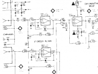
attach schematic of cd850
any suggestions either yeh or nay
Or am i flogging a dead horse
I was looking at my cd850 and thinking of next upgrade
http://www.diyaudio.com/forums/showthread.php?postid=705744#post705744
when i noticed the diff on the output of the DAC.
gave me a thought, hmm, balanced to SE
or even use balance in on preamp (new i'd find a use for them)
i wonder what i could use instead of valves.
attach schematic of cd850
any suggestions either yeh or nay
Or am i flogging a dead horse
Attachments
Metalman,
Did you solve you hum?
I may be reading your schematics wrong, but this is how I do my pre-amp:
I did about everything the same, only I do not only switch my incoming signals, but also my incoming ground. This means one of the grounding resistors is shortcircuited by the switch. (or relays in my case).
This way you keep the incoming signals roughly about ground, but because of the differences in ohm value you decrease possible ground loops with external devices.
Greetings, Harry.
P.S., can wait to copycat your design!
Harry,
Yes I did solve my hum problem but in a very round about way. Because it was inaudible at my normal listening levels, and because I could not isolate the source of it, I decided to take a break from hunting it down and just lived with it for awhile. Then one day I went back and checked for the hum again and it was gone! I scratched my head, and decided to reconfigure to a simpler switching arrangement, and the hum came back. The only thing I had changed was the wiring connections to my input switch. Insight finally arrived, and I realized that I had used a rather heavy solid strand piece of wire to connect the switch connections that represent signal grounds together, and in the process of soldering it on, which required a fair deal of heat, I had been heat oxidizing the silver switch contacts for those pins introducing unwanted resistance into the grounding path. Over the couple of months of use while I was ignoring the hum, the repetetive changing of switch positions had rubbed the oxide off thus eliminating the hum.
So, just to be extra perfectionist, I have replaced the switch, and used a separate fine guage wire for each ground contact on the switch, thus avoiding the overheating of the switch during soldering, and now I have no problems at all.
Isn't it always the simplist thing that trips you up, in this case trying to avoid some extra wiring by taking a shortcut. At least I learned another valuable lesson.
I am quite excited now as I am very close to finishing my 50W Aleph-X monoblocks, and I can't wait to hear how they will play together.
Cheers, Terry
Beautiful work. Thanks for sharing with us.
I'm in the middle of a preamp, and was considering improvements to the bosoz and was happy to rediscover this thread.
I'm not even an engineer, so take my comments and questions with that in mind, but I was considering a current mirror or two current sources on the pos supply, then saw that you cascoded instead. What improvement did you think the cascode would/does bring. I understand that cascode loading the fets makes them faster and they don't see the full voltage drop, but I didn't see that as the peformance limiter in this situation. My thoughts were increasing the linearity and gain with bjt current mirror would increase the gain so you coould use a little more feedback, or I might need to use 2 current sources because I don't know what side is the master and slave.
Or was it more an exercise than anything. I would be very interested in any insight or enlightenment to my incorrect assumtions.
Thanks
Metalman,
Thanks for your hum explanation. I would never have thought about overheating and degrading. A warned man counts for two as they say here in Holland.
I myself just about finished my Aleph 5. Finishing will take a while, because when I tested it, it never got disconnected again from my speakers. And I already sold my other amp after one evening of listening. 😀
Now I am starting with a pre-amp (although relays based, I want to switch on/off pre and main with a WAF able remote). Next will probably be a D1, then (or together with) an Aleph X 50Watt.
Greetings, Harry.
Originally posted by Brian Donaldson
What improvement did you think the cascode would/does bring. I understand that cascode loading the fets makes them faster and they don't see the full voltage drop, but I didn't see that as the peformance limiter in this situation. My thoughts were increasing the linearity and gain with bjt current mirror would increase the gain so you coould use a little more feedback, or I might need to use 2 current sources because I don't know what side is the master and slave.
The cascode has two benefits:
First as you pointed out, it increases the bandwidth at high frequencies, achieving both amplitude and phase linearity out to about 200kHz;
Second, by fixing the voltage across the gain transistors it improves their linearity (reduces their inherent distortion) so that less feedback is required for good performance, thus avoiding such problems as Transient Intermodulation Distortion (TIM) that high levels of global negative feedback can cause. Also, although higher feedback improves amplitude linearity, my understanding is that it tends to cause significant phase shift in the high frequencies.
As I knew that most all of my source components are single ended for the near future, I cascoded mostly to get better performance when using the preamp as a single-ended to balanced converter, where the SuSy isn't providing any benefit.
I should mention that you don't need to use mosfets for the cascode. BJT's would work equally well for the cascode.
Why one CCS vs. two or more? Well, I don't know the answer to that, and I have been scratching my head and intending to ask Nelson that very question. I beleive one benefit is increased efficiency, but I suspect there might be others.
The sonic benefit is quite positive. I had a chance to do a head to head comparison against a standard BZLS. My preamp retains all of the smoothness / naturalness of the BZLS, but is also more detailed with a more focused soundstage compared to the standard BZLS, somehow without being any more bright.
Originally posted by harryeng
A warned man counts for two as they say here in Holland.
&
Now I am starting with a pre-amp (although relays based, I want to switch on/off pre and main with a WAF able remote). Next will probably be a D1, then (or together with) an Aleph X 50Watt.
I like that saying! I suspect it appeals to me because I am Dutch (albeit 2 generations removed). I too have been studying remote control design, relay source selection and electronic volume control schemes. I'm a typical engineer in that regard, my mind does not like to be idle.
One variation to my original design that I have been thinking on was inspired by Nelson's talk of an Aleph J. I was thinking about using JFET's cascoded by either mosfets or BJT's. The approach would have to be carefull to keep the power level on the JFET's low, but it seems conceptually possible.
Cheers, Terry
- Status
- Not open for further replies.
- Home
- Amplifiers
- Pass Labs
- CC-CCS-X-BZLS: It's alive!